Mounting and connecting the junction box, Mounting and connecting the junction box -2, Attention – Rockwell Automation 2727-M7P20D1P1, -M7P20D1Q2,-M7P20D1Q3 MobileView Machine Terminal MT750 User Manual
Page 18
Publication 2727-UM003D-EN-P
2-2 Terminal Connections
Mounting and Connecting
the Junction Box
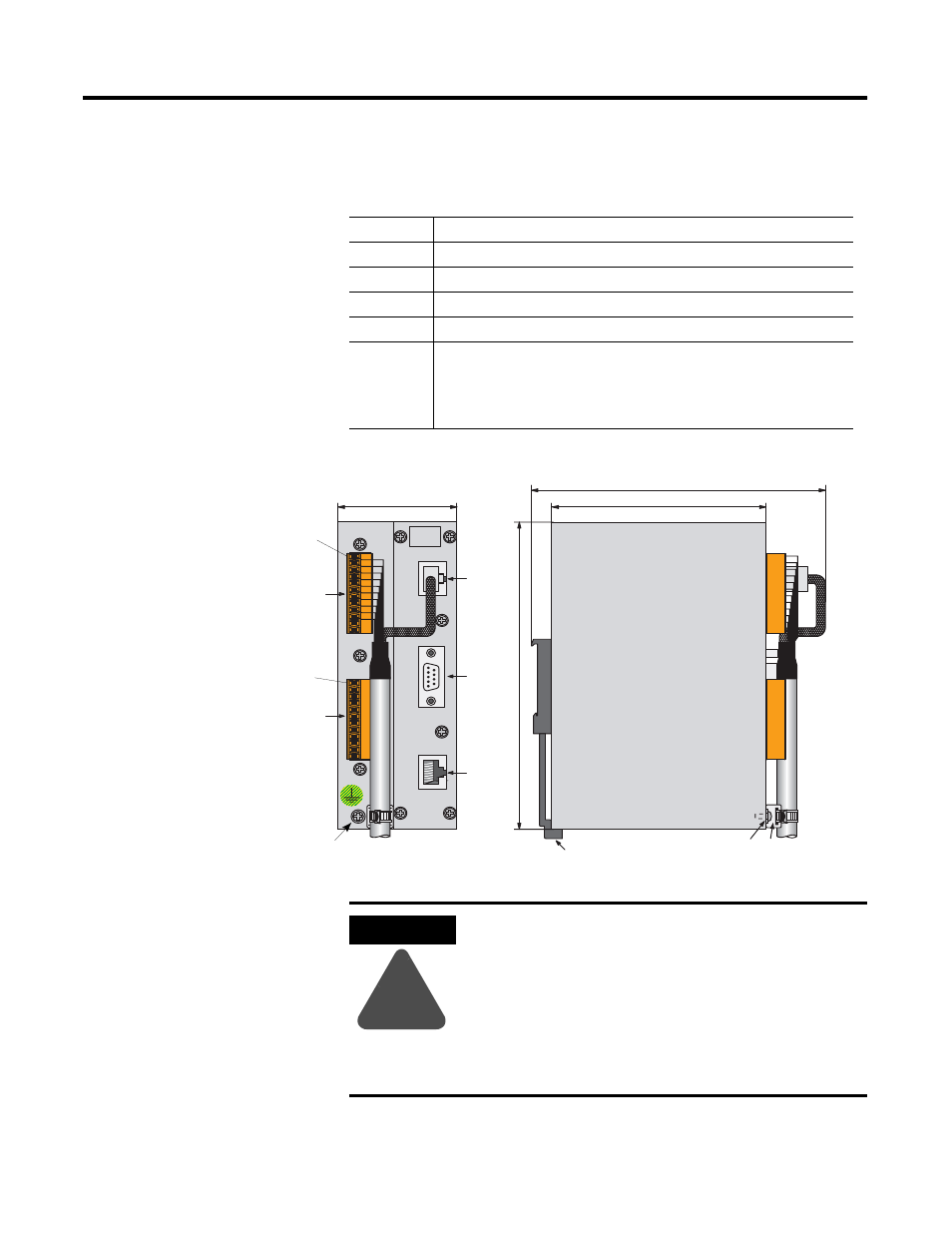
The MobileView Junction Box (2727-MRJB1) integrates the
MobileView terminal into the control system. It mounts on a DIN rail
inside an enclosure and has the following connectors:
Connectors
Description
S1
RJ-45 jack for connecting the MobileView data lines.
S2
9-pin DSUB female connector (for future use).
S3
RJ-45 jack to Ethernet network.
X1
12-pin male connector for connecting the Junction Box Cable.
X2
12-pin male connector (shipped with a female terminal block connector) for
connecting the:
• 24V dc power supply
• emergency stop switch
• enabling switches
24V D C
ON LY
TER M IN AL IN
R S422 OUT
ETH ER N ET O U T
+24V
GND
ES 1+
ES 1-
ES 2+
ES 2-
ED1 +
ED1 -
ED2 +
ED2 -
+24V
GND
ES 1+
ES 1-
ES 2+
ES 2-
ED1 +
ED1 -
ED2 +
ED2 -
X2
(with Female
Terminal Block
Connector K4)
S1
S2
S3
Junction Box
Pin 1, 24V dc
Pin 1, 24V dc
16
2 mm
(6
.4
in
.)
X1
(with Female
Terminal Block
Connector K3)
108 mm (4.25 in)
150 mm (5.91 in)
60 mm (2.36 in)
DIN Rail Latch
Grounding Screw
Strain Relief
for Cable
Grounding Screw
ATTENTION
!
The MobileView Junction Box and the MobileView
terminal meet the safety class III in accordance with
EN 61131-2 and EN 50178.
When connecting the terminal, make sure all
voltages connected to the MobileView terminal are
safety extra low voltages and isolated from the low
voltage supply system by a safety transformer or a
similar safety component.