I/o interface diagram, Drive setup, I/o interface diagram drive setup – Rockwell Automation 2092-DAx Ultra1500 Digital Servo Drive Quick Start User Manual
Page 5
Ultra1500 Digital Drives Quick Start 5
Publication 2092-QS001D-EN-P — July 2005
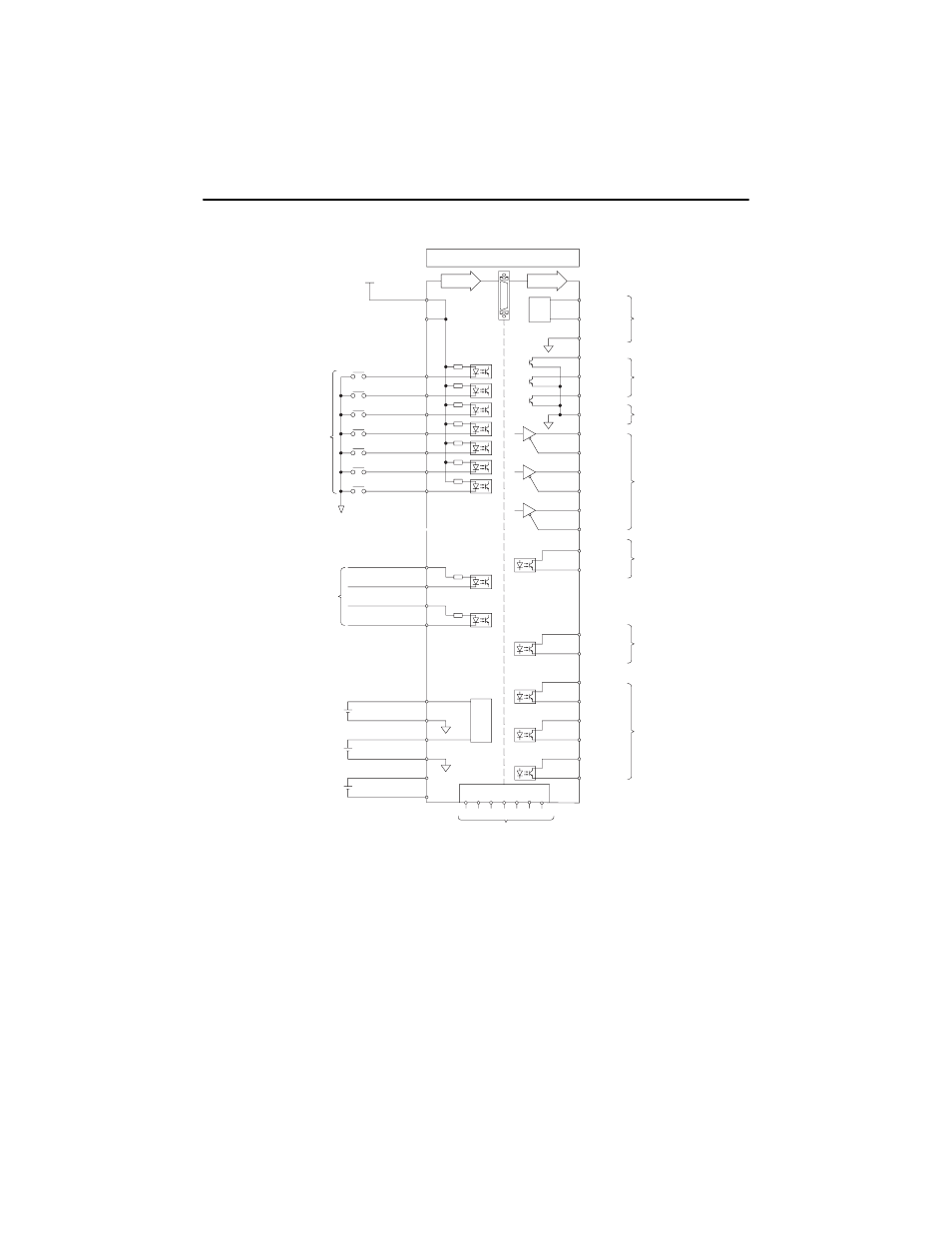
I/O Interface Diagram
Drive Setup
The Setup Wizard found in the Commands menu of Ultraware software (v1.60 or higher) is a quick
way to configure your Ultra1500 servo system. A step-by-step procedure assists in the selection of
controls and motor to be configured with the Ultra1500 drive, and then tunes the assembled system.
For detailed hardware, interconnect, and application related information about Ultra1500 drives, refer
to the following:
•
The on-line help provided with Ultraware software, v1.60 or higher (catalog no. 2098-UWCPG).
•
The Ultra1500 Digital Drive User Manual (publication 2092-UM001x-EN-E).
VCMD-
BAT+
BAT-
VCMD+
BX-
INPUT7
INPUT6
AX-
BX+
AX+
49
25
A/D
19
14
20
9
8
12
13
11
OUTPUT3+
OUTPUT3-
48
FAULT+
FAULT-
Z-PULSE+
Z-PULSE-
OUTPUT1+
IM+
IM-
BM-
BM+
OUTPUT2-
OUTPUT2+
OUTPUT1-
18
45
46
41
42
43
47
44
31
33
32
17
34
+24VIN
24V Power
INPUT3
INPUT4
INPUT1
INPUT2
INPUT5
D/A
2
6
5
4
3
7
1
15
26 35
FAULT1
AM+
AM-
FCOM
23
39
30
29
40
38
37
27
FAULT3
FAULT2
28
ICMD+
ICMD-
22
21
ACOM
CN1
Input
Output
Position
Command
Current Command
-10V to +10V
3.6V Backup Battery
for Absolute Encoder
Binary
Fault
Code
Output
Buffered
Encoder
Output
24V Ground
AOUT1
AOUT2
Binary Fault
Code Ground
36 50
Encoder
Marker
Pulse
Fault
Output
24V
Active Low
Programmable
Digital Inputs
24V
Programmable
Digital
Outputs
Reserved
Analog Output
-10V to +10V
Speed Command
-10V to +10V
16 24