Power wiring diagram – Rockwell Automation 2092-DAx Ultra1500 Digital Servo Drive Quick Start User Manual
Page 4
4 Ultra1500 Digital Drives Quick Start
Publication 2092-QS001D-EN-P — July 2005
Figure 4
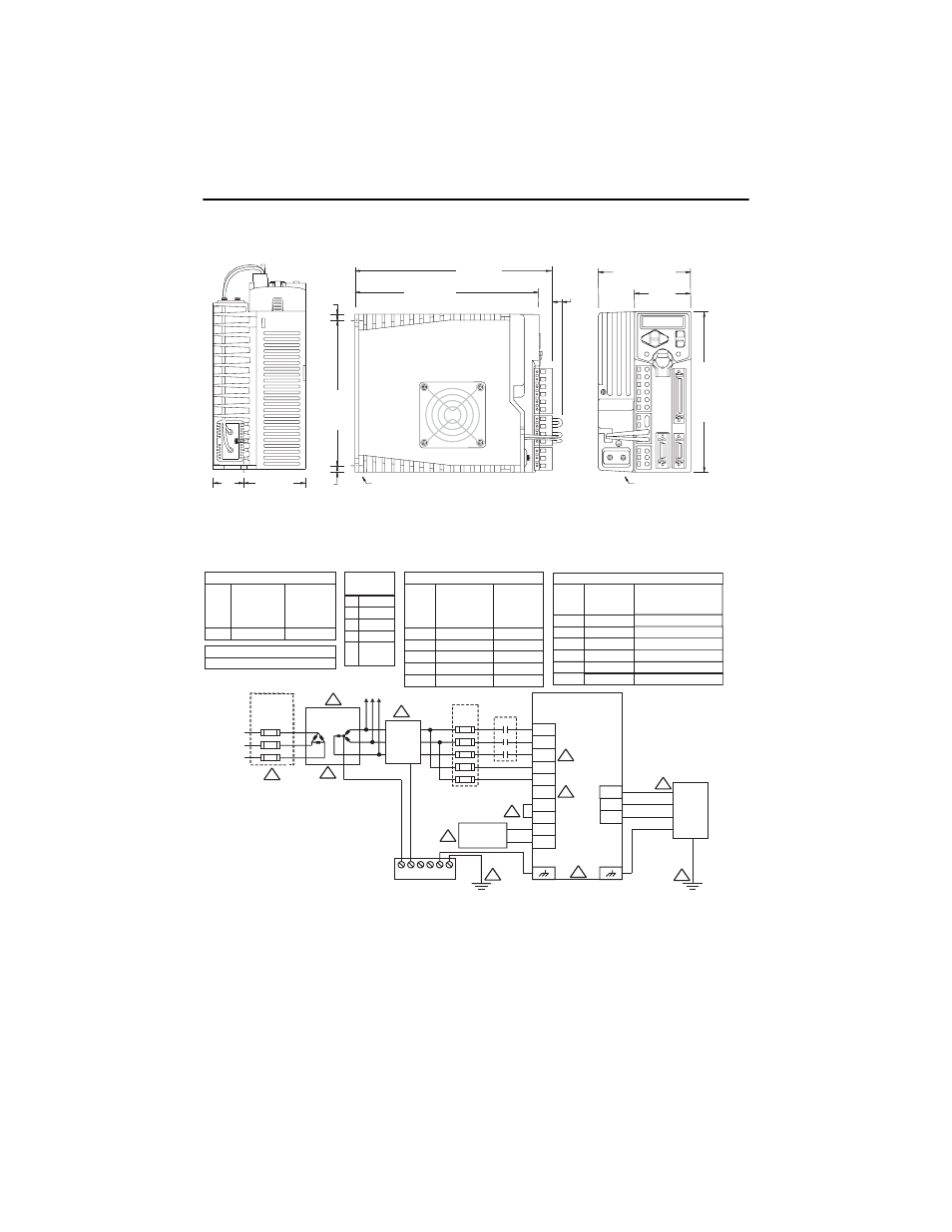
Dimensional Outline Drawing for 2092-DA4 and 2092-DA5
Power Wiring Diagram
63.0
(2.48)
27.0
(1.06)
5.0
(0.20)
5.0
(0.20)
145.0
(5.70)
Mounting hole (top) and slot
(bottom) require M5 x 10 bolts
Chassis ground
terminals (2)
12.0
(0.47)
185.0
(7.28)
198.0
(7.80)
55.0
(2.17)
155.0
(6.10)
90.0
(3.54)
Dimensions are in millimeters (inches). Drives are designed to metric dimensions; inches are a mathematical conversion.
11. Refer to manual included with motor for power, feedback, and brake interconnect information (pinouts and/or wire colors).
12. Wire sizes are minimum recommended values. Local regulations should be observed.
MOTOR
MOTOR POWER WIRES U, V, W, AND GND
MOTOR POWER
MATING CONNECTOR
CONTACT SIZE
TL-SERIES 2.5 mm (14 AWG)
2
MINIMUM
RECOMMENDED
POWER WIRE SIZE
(75 C COPPER)
O
2.5 mm (14 AWG)
2
TERMINAL STRIP ACCEPTABLE WIRE RANGES
0.8 - 2.5 mm (28 - 12 AWG)
2
PIN
SIGNAL
A
B
C
U
V
W
D
MOTOR POWER
CONNECTOR
MOTOR CASE
(GROUND)
INPUT POWER WIRES
2092-DA1 L1, L2, L1C, L2C, GND
2.5 mm (14 AWG)
2
2092-DA2
2.5 mm (14 AWG)
2
2092-DA3
2.5 mm (14 AWG)
2
2092-DA4
2.5 mm (14 AWG)
2
2092-DA5
2.5 mm (14 AWG)
2
DRIVE
TERMINALS
MINIMUM
RECOMMENDED
POWER WIRE SIZE
(75 C COPPER)
O
L1, L2, L1C, L2C, GND
L1, L2, L1C, L2C, GND
L1, L2, L3, L1C, L2C, GND
L1, L2, L3, L1C, L2C, GND
DIGITAL DRIVE MODULE INPUT CURRENT REQUIREMENTS
DRIVES
2092-DA1
2092-DA2
2092-DA3
2092-DA4
TERMINALS
L1, L2, GROUND
L1, L2, GROUND
L1, L2, GROUND
L1, L2, L3, GROUND
MAXIMUM
CURRENT REQUIREMENT,
(AMPS, AC RMS)
3.3 AMPS AC at 200-240 VOLTS AC
5.5 AMPS AC at 200-240 VOLTS AC
8.0 AMPS AC at 200-240 VOLTS AC
11.0 AMPS AC at 200-240 VOLTS AC
2092-DA5 L1, L2, L3, GROUND 15.0 AMPS AC at 200-240 VOLTS AC
ALL
L1C, L2C
2.0 AMPS AC at 200-240 VOLTS AC
6. High-frequency grounding, using heavy braided wires, should connect together the electronic equipment, electrical enclosure, machine frame, and motor housing.
5. Internal shunt resistor is present only on 2092-DA3, 2092-DA4, and 2092-DA5 drives. B1 and B2 should be left disconnected on 2092-DA1 and 2092-DA2 drives.
3. Isolation transformer is optional. If used, the secondary of the transformer must be grounded.
10. 2092-DA1 and 2092-DA2 drives have one grounding screw on the heatsink. 2092-DA3, 2092-DA4, and 2092-DA5 drives have two grounding screws on the heatsink.
8. 2092-DA1, 2092-DA2, and 2092-DA3 drives are single-phase AC input drives; input power is not connected to L3 on these drives. .
Notes:
7. If the power factor or harmonic distortion needs improvement, the jumper from P1 to P2 can be replaced with an inductor.
9. DC Bus Voltage connection - not an AC power input.
2. If using an isolation transformer, ensure the phase to neutral/ground voltage does not exceed the input ratings of the drive.
1. A supply disconnecting device is required for maintenance and safety. Local regulations should be observed.
4. AC line filter and shielded motor cable are to be used for improving the drive module's electromagnetic compatiblity (EMC), and are required to meet European EMC directive.
Wiring between the drive module and filter should be kept as short as possible. The common ground bus bar should be as close to the drive as possible.
CAUTION: AC line filters have large leakage currents and require discharge time upon power removal.
Tighten the ground terminal screw(s) to 1.25 Nm (11 lbs-in.)
L1
ULTRA1500
L2
L3
L1C
L2C
N
P1
P2
B1
B2
M1
AC
LINE
FILTER
SHUNT
RESISTOR
U
V
W
MOTOR
FUSE
BLOCK
1:1 ISOLATION
TRANSFORMER
FUSED
DISCONNECT
OR CIRCUIT
BREAKER
230V
3-PHASE
AC LINE
50/60 HZ
DRIVES
2092-DA1
2092-DA2
2092-DA3
2092-DA4
2092-DA5
2
8
4
7
3
5
9
6
1
10
11
GROUND BAR
6