Specifications, Appendix, Figure a.1 alec front panel – Rockwell Automation 4100 ALEC AXIS LINK ENCODER CONVERTER User Manual
Page 49: Alec
41
Publication 4100-5.3 - June 1999
Appendix
A
Specifications
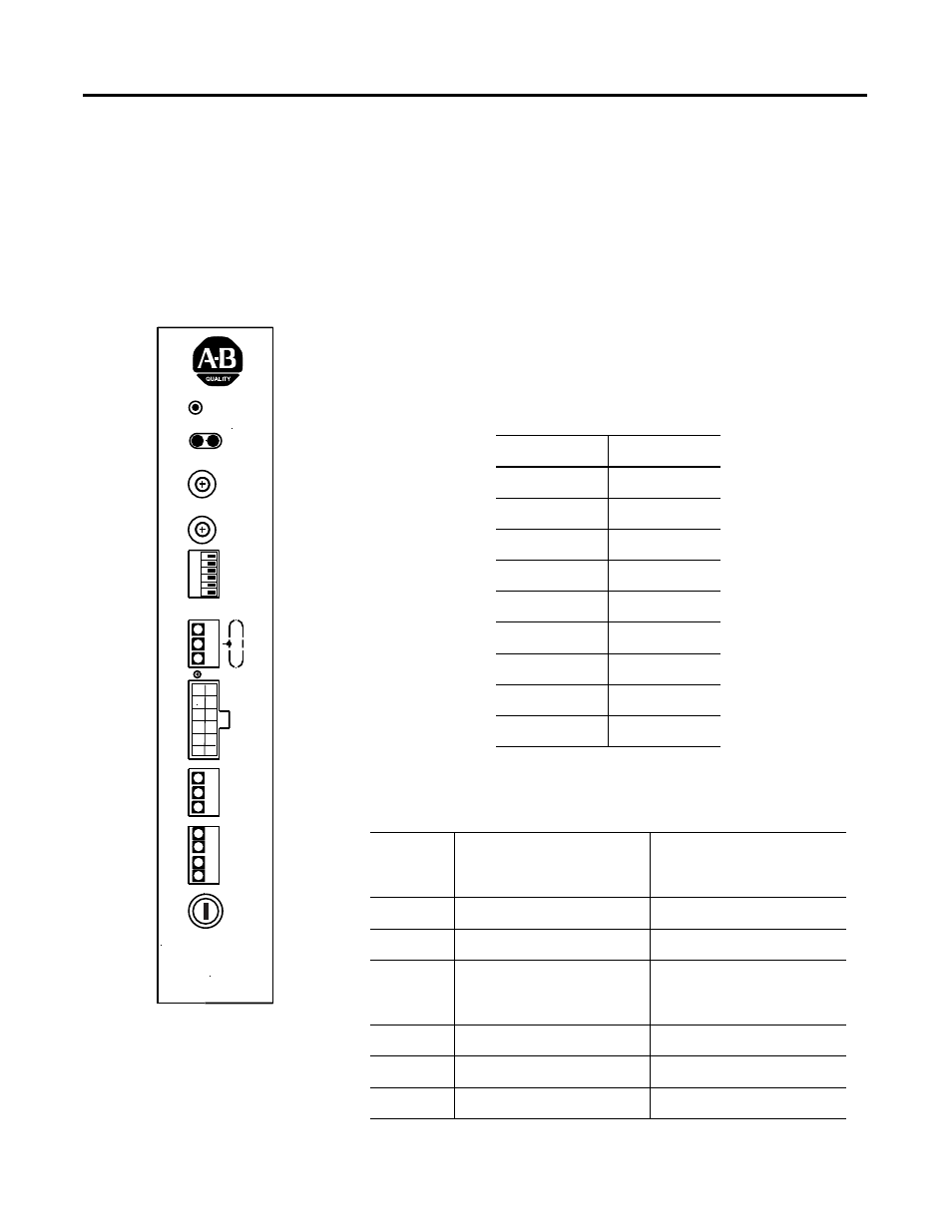
Figure A.1 ALEC Front Panel
Figure A.1 shows the front panel layout showing the dip switches, pin
locations, rotary switches, and LEDs for the ALEC. The following
tables provide explanations for the rotary switches, dip switches, and
pins.
ALEC
Fuse
Common
24V DC
F
ault P
o
w
e
r
Rela
y Input
Registr
ation
Input
Incremental
Encoder Input
Encoder OK
AxisLink
1
2
AxisLink
Address
Mode
AL
CPU OK
Reset
12V/5V
Extd Node On/Off
Enc. Fault On/Off
Extd Length On/Off
Extd Term 1 On/Off
Extd Term 2 On/Off
12
3
4
5
6
0
8
3
B
2
4
5
6
7
9
A
C
D
E F
1
0
8
3
B
2
4
5
6
7
9
A
C
D
E F
1
0
8
3
B
2
4
5
6
7
9
A
C
D
E F
1
0
8
3
B
2
4
5
6
7
9
A
C
D
E F
1
0
8
3
B
2
4
5
6
7
9
A
C
D
E F
1
0
8
3
B
2
4
5
6
7
9
A
C
D
E F
1
Table A.1 Mode Rotary Switch Settings
Switch Setting
Description
0
250 Hz
1
300 Hz
2
350 Hz
3
400 Hz
4
500 Hz
5
700 Hz
6
850 Hz
7
1000 Hz
8
−
F
Reserved
Table A.2 DIP Switches
Switch
Number
ON
(Switch set to Left position)
OFF
(Switch set to Right
position)
1
12 Volt
5 Volt
2
Extended Node Addressing (16)
Standard Node Addressing (8)
3
Encoder Fault Enabled- Detects
encoder fault and opens Fault
Relay
Encoder Fault Disabled - Fault
relay is not opened if Encoder
faults.
4
Extended Length
Standard Length
5
Extended Length Termination 1
Standard Length Termination 1
6
Extended Length Termination 2
Standard Length Termination 2