Alec mechanical specifications, Figure 1.1 alec front panel – Rockwell Automation 4100 ALEC AXIS LINK ENCODER CONVERTER User Manual
Page 16
Publication 4100-5.3 - June 1999
8 Overview
The optically isolated encoder input accepts 5 Volt differential
quadrature signals from standard incremental encoders. 5V and 12V
DC are available from the ALEC for powering the encoder. An
optically isolated registration input which latches encoder position is
provided for direct interface to a position registration sensor. This
input can be used directly with 5V or 24 V devices.
AxisLink communication with IMC S Class motion controllers is
controlled by a dedicated communication chip. An address selector
switch is provided on the front panel to set the address of the ALEC
on AxisLink. A front panel AxisLink status LED (AL) is also provided.
The ALEC includes a switching power supply with fused 18-36V DC
input which provides separate outputs for the optically-isolated
encoder input and AxisLink communication channel.
ALEC Mechanical
Specifications
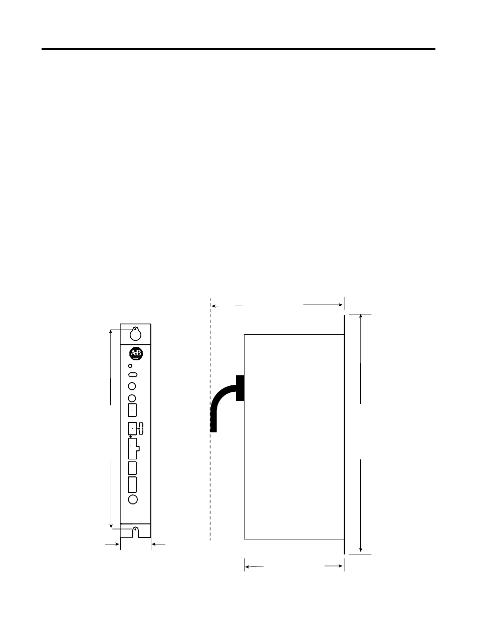
Figure 1.1 shows the placement and labeling of major items on the
ALEC front panel as well as the physical dimensions.
Figure 1.1 ALEC front panel
285.75 mm (11.25 in.)
Use 1/4 -20 or M6
bolt (typical 2 places)
48.26 mm (1.9 in.)
190.5 mm (7.5 in.) with
cable clearance
300.23 mm (11.82 in.)
130.175 mm (5.125 in
.)
ALEC
Fuse
Common
24V DC
F
ault P
o
w
e
r
Rela
y Input
Registr
ation
Input
Incremental
Encoder Input
Encoder OK
AxisLink
1
2
AxisLink
Address
Mode
AL
CPU OK
Reset
12V/5V
Extd Node On/Off
Enc. Fault On/Off
Extd Length On/Off
Extd Term 1 On/Off
Extd Term 2 On/Off