Rockwell Automation 1792D-12BT4PE ArmorBlock MaXum 12 In/4 Out Module with Ground Lug User Manual
Page 7
ArmorBlock MaXum 12 Input/ 4 Output Module With Ground Lug 7
Publication
1792D-IN056A-EN-P - October 2004
Connect the Input / Output Cord Sets to the MaXum Module
This module uses 5 pin micro (12mm) style PCB mounted connectors.
Eight micro caps cover the connectors on your module. Remove the
caps and connect your cord sets to the appropriate ports. This
product has two inputs or outputs per I/O connector. Use a “Y”
splitter cable for access to all I/O connections.
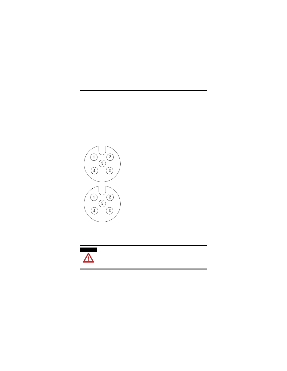
Use the micro caps to cover and seal unused ports. Pinout diagrams
for the connectors are shown below.
Molded I/O cables with LEDs embedded in the connector are
incompatible with MaXum universal sink/source inputs.
WARNING
If you connect or disconnect the communications cable
with power applied to this module or any device on the
network, an electrical arc can occur. This could cause an
explosion in hazardous location installations.
Input Micro-Connector
(view into socket)
Pin 1 Sensor Source voltage
Pin 2 Input B
Pin 3 Return Logic Ground
1
Pin 4 Input A
Pin 5 PE
Output Micro-Connector
(view into socket)
Pin 1
Not Used
Pin 2 Output B
Pin 3 Auxiliary Power Ground
Pin 4 Output A
Pin 5 PE
1
Logic Ground is approximately 0.4V above DeviceNet V- measured at the module.
41452