Relay contact modules – Rockwell Automation 1746-XXXX SLC 500 Digital I/O Modules Installation Instructions User Manual
Page 42
42 SLC 500 Digital I/O Modules
Publication 1746-IN027D-EN-P - December 2012
Careful wire routing within the enclosure helps cut down electrical noise between I/O lines.
Refer to the SLC 500 Modular Hardware Style User Manual, publicatio
recommended wiring procedures for TTL modules.
Limit cable length to 3 m (10 ft) per point for outputs in standard environments.
Refer to Allen-Bradley Programmable Controller Wiring and Grounding Guidelines,
publication
for complete information.
Relay Contact Modules
ATTENTION: To avoid potential damage to TTL modules, handle them by the ends of the module,
not metallic surfaces. Electrostatic discharges can damage the module. Take care to prevent
exposure of terminals or components to electrostatic charges.
WARNING: Exposure to some chemicals may degrade the sealing properties of materials used
in the following devices: Relay Epoxy.
It is recommended that the user periodically inspect these devices for any degradation of
properties and replace the module if degradation is found.
Specifications – 1746-OW4, 1746-OW8, 1746-OW16, and 1746-OX8
Attribute
Value
1746-OW4
(2)
1746-OW8
(2)
1746-OW16
(2)(3)
1746-OX8
(2)(3)
Voltage category
AC/DC Relay
Number of outputs
4
8
16
8
Points per common
4
4
8
Individually isolated
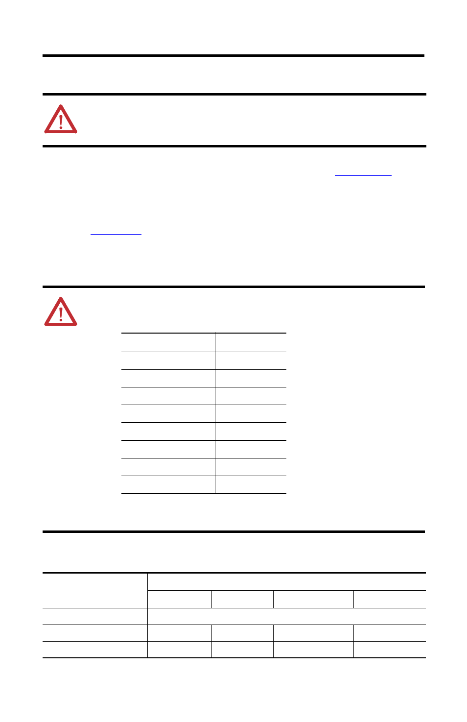
Catalog
Relay
1746-OX8
K1…K8
1746-IO4
K1 and K2
1746-IO8
K1…K4
1746-IO12
K1…K6
1746-IO12DC
K1…K6
1746-OW4
K1…K4
1746-OW8
K1…K8
1746-OW16
K1…K16