Default configuration, Interpret status indicators, Troubleshooting – Rockwell Automation 1771-IXE Installation Instructions User Manual
Page 9: Interpret status indicators troubleshooting
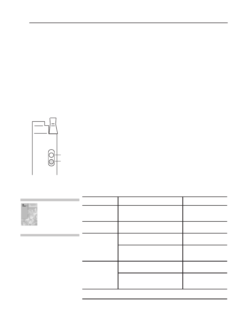
RUN
FLT
TC/MV
Green RUN indicator
Red FAULTindicator
Thermocouple/Millivolt Input Module
9
Publication 1771Ć5.64 - October 1998
Default Configuration
If a write block of five words with all zeroes is sent to the module,
default selections will be:
•
Millivolt input
•
one input type
•
temperature in
o
C
•
BCD data format
•
no real time sampling (RTS) (50ms)
•
no alarming
The front panel of the thermocouple/mV input module contains a
green RUN indicator and a red FAULT indicator. At power-up, the
module momentarily turns on the red indicator as a lamp test, then
checks for:
•
correct RAM operation
•
EPROM operation
•
EEPROM operation
•
a valid write block transfer with configuration data
If there is no fault, the red indicator turns off.
Thereafter, the module lights the green RUN indicator when
operating without fault, or lights the red FAULT indicator when it
detects fault conditions. If the red FAULT indicator is on, block
transfers will be inhibited.
Possible module fault causes and corrective action is described in
the following table.
Indicators
Probable Cause
Recommended Action
Both indicators are OFF No power to module
Possible short on the module
LED driver failure
Check power to I/O chassis.
Recycle as necessary.
Replace module.
Red FLTON and
Green RUN is ON
Microprocessor, oscillator or EPROM failure
Replace module.
Red FLTON
If immediately after power-up, indicates RAM
or EPROM failure.
1
Replace module.
If during operation, indicates possible
microprocessor or backplane interface
failure.
1
Replace module.
Green RUN is flashing
Power-up diagnostics successfully
completed.
Normal operation.
If LED continues to flash, and write block
transfers (BTW) cannot be accomplished, you
have a possible interface failure.
Replace module.
1
When red LED is on, the watchdog timer has timed out and backplane communications are terminated. Your user program should
monitor communication.
For detailed troubleshooting
information, see
Troubleshooting" in your
Thermocouple/mV Input
Module User Manual
(publication 1771Ć6.5.130).
Interpret Status Indicators
Troubleshooting