Thermocouple/millivolt input module accuracy – Rockwell Automation 1771-IXE Installation Instructions User Manual
Page 12
Thermocouple/Millivolt Input Module
12
Publication 1771Ć5.64 - October 1998
Backplane Power
850mA @ 5V;
Power Dissipation
4.25 Watts maximum
Thermal Dissipation
14.5 BTU/hr
Environmental Conditions
Operating Temperature:
Rate of Change:
Storage Temperature:
Relative Humidity:
0 to 60
o
C (32 to 140
o
F)
Ambient changes greater than 0.5
o
C per minute may temporarily
degrade performance during periods of change
-40 to 85
o
C (-40 to 185
o
F)
5 to 95% (without condensation)
Conductors
Wiring
Category
Use Belden 8761 shielded twisted pair for mV
Use thermocouple manufacturer recommended shielded
thermocouple wire for all thermocouple inputs.
2
Field Wiring Arm
Cat. No. 1771-WI
Keying
Between 20 and 22
Between 24 and 26
Agency Certification
(when product is marked)
•
CSA certified
•
CSA Class I, Division 2, Groups A, B, C, D certified
•
UL listed
•
CE marked for all applicable directives
User Manual
Publication 1771Ć6.5.130
Refer to publication 1770Ć4.1, Industrial Automation Wiring and Grounding Guidelines for Noise Immunity.
The accuracy of your thermocouple readings depends on:
module accuracy
lead resistance effect
accuracy of the thermocouple
Use the calibration procedure in Chapter 7 to adjust your module to
compensate for your specific environment.
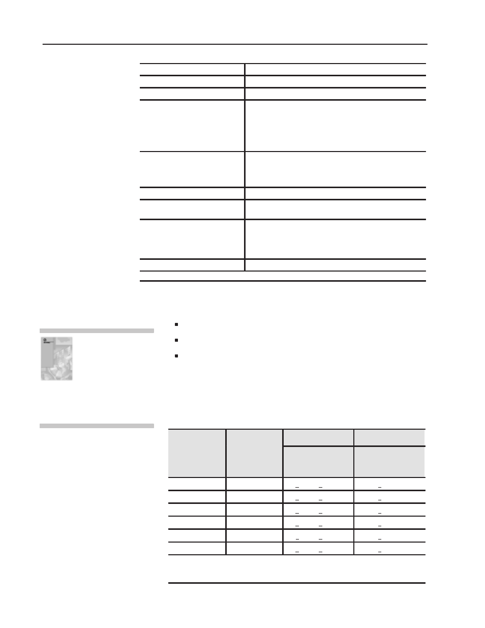
Thermocouple Range Accuracy Based on Temperatures
Above 0
o
C
Column A
Column B
Thermocouple
Type
Temperature
Range
o
C
Max Error @
Calibration
Temperature (25
o
C)
1
Temperature Drift
o
C/
o
C (0-60
o
C)
or
o
F/
o
F (32-140
o
F)
E
-270 to 1000
+0.74
o
C/+1.08
o
F
+0.0400
J
-210 to 1200
+0.78
o
C/+1.10
o
F
+0.0423
K
-270 to 1380
+0.77
o
C/+1.15
o
F
+0.0640
T
-270 to 400
+0.77
o
C/+1.17
o
F
+0.0183
R
-50 to 1770
+1.50
o
C/+2.11
o
F
+0.0914
S
-50 to 1770
+1.50
o
C/+2.31
o
F
+0.0926
1
Error is specified from 0
o
C (32
o
F) to the maximum range of the thermocouple. Error
does not include thermocouple error (see appendix F). The error does include cold
junction compensation errors.
Use the calibration procedure
in Chapter 7, Module
Calibration, in your
Thermocouple/mV Input
Module User Manual
(publication 1771Ć6.5.130) to
adust your module to
compensate for your specific
environment.
Thermocouple/Millivolt
Input Module Accuracy