Configure the module – Rockwell Automation 1771-IXE Installation Instructions User Manual
Page 7
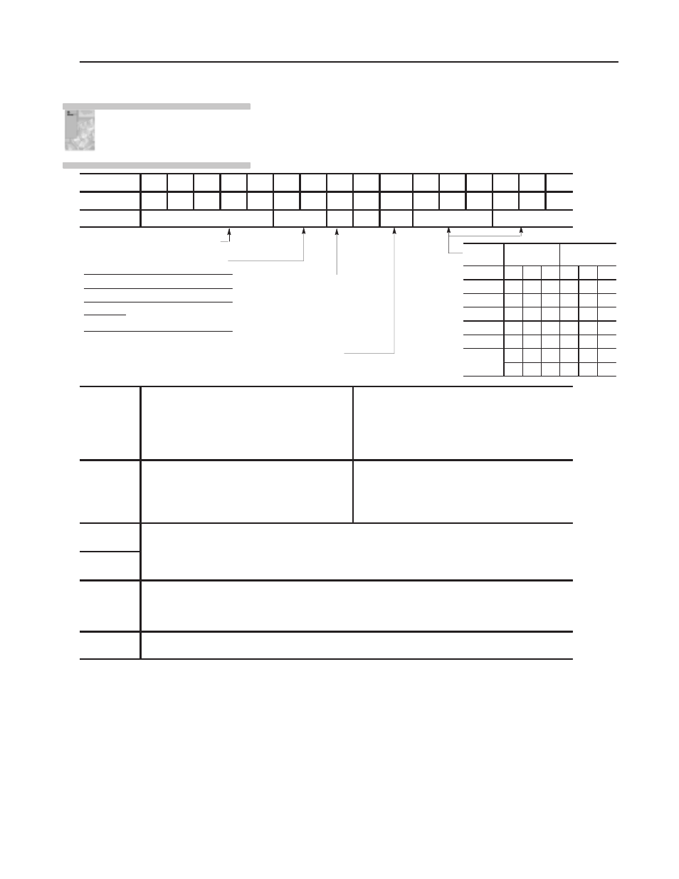
Temperature scale bit, when
set, reports temperature in
o
F;
when reset, in
o
C. The module
ignores this bit for millivolt
inputs.
Input Type Enable - When set to 0 bits 00-02 define input type for all
channels.
When set to 1 bits 00-02 defines input type for channels 1-4,
and bits 03-05 defines input type for channels 5-8.
Real time sampling - Default is no
RTS.
Data format - set to
match your processor.
BCD (default)
Two's complement
binary
Signed magnitude binary
Bit 10
(12)
Bit 09
(11)
0
0
0
1
1
0
1
1
Thermocouple/Millivolt Input Module
7
Publication 1771Ć5.64 - October 1998
You must configure the module to conform to the analog device and
specific application that you have chosen. Use the configuration
information below to configure your module to your specifications.
WordDec. Bit
17
16
15
14
13
12
11
10
07
06
05
04
03
02
01
00
WordOctal Bit 17
16
15
14
13
12
11
10
07
06
05
04
03
02
01
00
1
Sample Time
Format
T
0
E
Input Type
Input Type
Input
Type
Bits
05 04
03
Bits
02 01 00
Millivolt
0
0
0
0
0
0
E
0
0
1
0
0
1
J
0
1
0
0
1
0
K
0
1
1
0
1
1
T
1
0
0
1
0
0
R
1
0
1
1
0
1
S
1
1
0
1
1
0
1
1
1
1
1
1
2
Not Used
Channel alarm enable bits tell the module which channel
alarm values are activated. Set bit 00 for alarm(s) in
channel 1, and set alarm(s) in words 4 (low alarm) and 5
(high alarm). Repeat the procedure for setting alarms in
channels 2 thru 8 (bits 01-07 and words 6-19
respectively).
3
High Alarms Polarity (one bit per input channel) - tell
the module the sign of the values that you enter in high
alarm words: set for negative, reset for positive. Bits
10-17 represent words 5, 7, 9, 11, 13, 15, 17 and 19 for
channels 1 thru 8, respectively.
Low Alarms Polarity (one bit per input channel) - tell
the module the sign of the values that you enter in low
alarm words: set for negative, reset for positive. Bits
00-07 represent words 4, 6, 8, 10, 12, 14, 16, and 18 for
channels 1 thru 8, respectively.
4, 6, 8, 10,
12, 14, 16, 18
Low andhigh channel alarm values that you enter via the terminal in BCD are converted automatically by the
module to its own format.
5, 7, 9, 11,
13, 15, 17, 19
Store low and high channel alarms in pairs, low alarm values in even-numbered words, high alarm values in
odd-numbered words. For example, store channel 1 low and high alarm values in words 4 and 5, respectively.
20, 21, 22,
23, 24, 25,
26, 27
Calibration words are a composite of two independent bytes for each channel. Enter calibration data in signed
magnitude binary only. The most significant bit in each byte is the sign bit; set for negative, reset for positive.
Use the high byte (bits 10-17) for offset correction, the low byte (bits 00-07) for gain correction for each channel.
Use word 20 for channel 1 thru word 27 for channel 8.
28
Auto-calibration request word- used to automatically calibrate selected channels and save the calibration
constants in EEPROM.
For detailed configuration information,
see Module Configuration" in your
Thermocouple/mV Input Module User
Manual (publication 1771Ć6.5.130).
Configure the Module