Table 4.1 selecting the external resistor, Interpreting the status leds, Table 4.2 dh+ status led – Rockwell Automation 1784-PKTX_PKTXD Communication Card User Manual User Manual
Page 28: Interpreting the status leds -12
4-12 Connecting the Network Interface Card
Publication 1784-UM527B-EN-P - October 2003
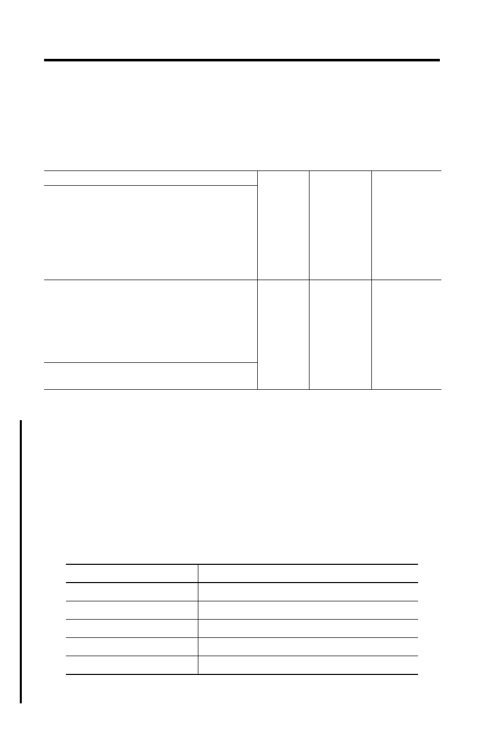
Table 4.1 Selecting the External Resistor
Interpreting the Status LEDs
What the LEDs mean depends on which protocol is running. Only the PKTXD uses both
LEDs. The left LED (labeled |) is for the top channel on a PKTXD and the other is for the
second, lower channel. A PKTX has only one channel (but multiple connectors depending on
protocol) so only one LED is used.
Table 4.2 explains the DH+ Status LED. Table 4.3 on page 4-13 explains the DH-485 Status
LED. Table 4.4 on page 4-13 explains the Remote I/O Scanner Mode LED.
The maximum number of:
If your remote I/O link:
use this
resistor
rating:
physical
devices
connected on
the link:
racks that you
can scan on the
link:
operates at 230.4 K bits
82
Ω
32
16
operates at 57.6 or 115.2K bit/s, and no devices listed
below are linked:
Scanners:
1771-SN; 1772-SD, -SD2;
1775-SR, -S4A, -S4B;
Adapters
1771-AS; 1771-ASB (series A only);
1771-DCM
Miscellaneous
1771-AF
connects to any device listed below:
150
Ω
16
16
Scanners
1771-SN; 1772-SD, -SD2;
1775-SR, -S4A, -S4B;
Adapters
1771-AS; 1771-ASB (series A only);
1771-DCM
Miscellaneous
1771-AF
operates at 57.6 or 115.2K bit/s, and you do not require
over 16 physical devices
Table 4.2 DH+ Status LED
LED State
Means
off
channel not online
blinking green
it is the only node on the network
solid green
online and receiving token
blinking red
duplicate node
solid red
failed selftest