Rockwell Automation 1791-I0VW USER MANUAL User Manual
Page 7
Introducing Block I/O
Chapter 1
1-2
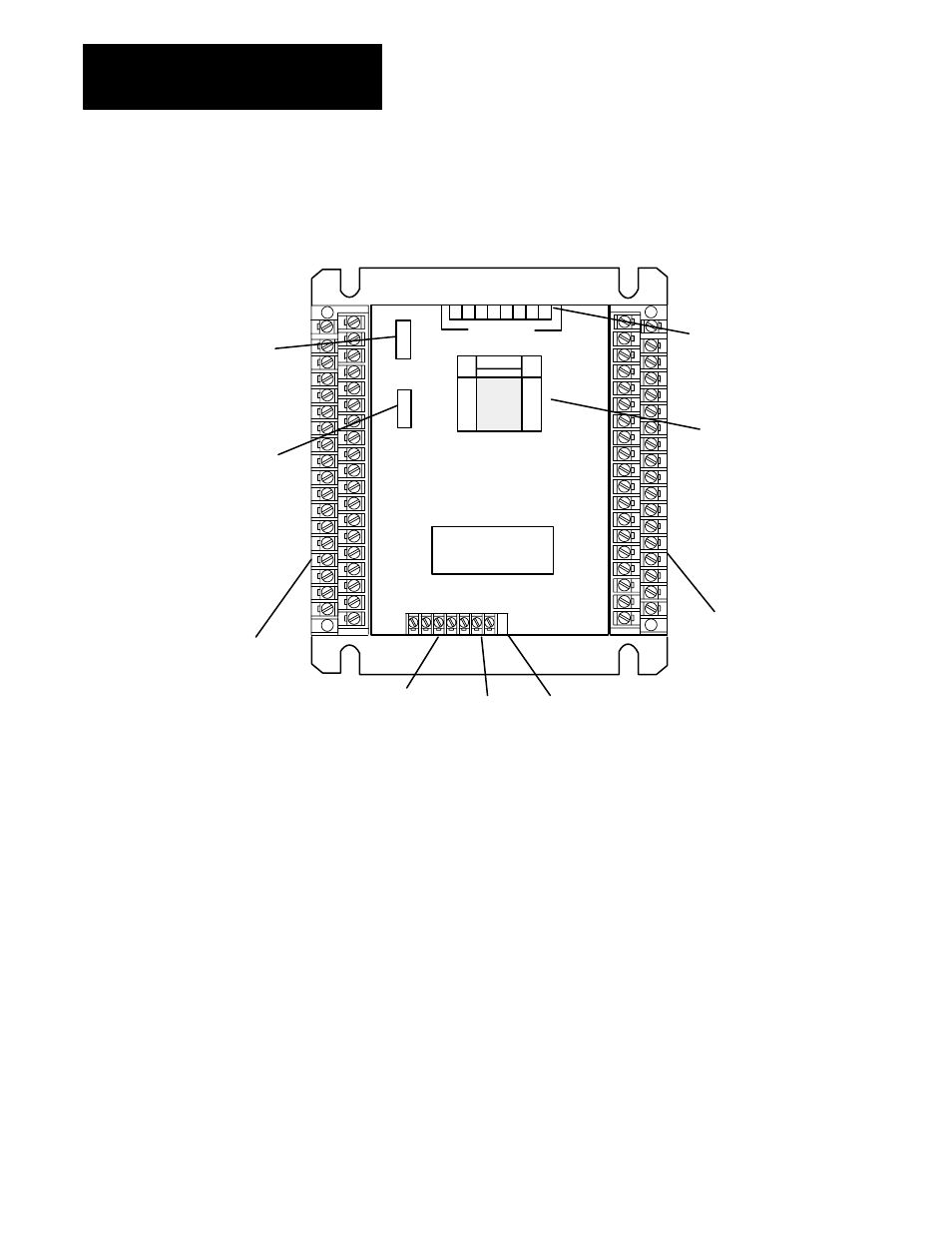
Figure 1.1
Major Features of the 1791ĆIOBW and ĆIOVW Block I/O Modules
(ĆIOBW shown)
POWER
ACTIVE
COMM
FUSE
RACK
ADDR
CONFIGURATION SWITCHES
1791ĆIOBW
64 POINT
24V DC DISTRIBUTED
I/O MODULE
8 7 6 5 4 3 2 1
CONFIGURATION
SWITCHES
Removable
Input Terminal
Blocks
Removable
Output Terminal
Blocks
Configuration Switches
(on top of unit)
Input/Output
Status LED
Array
Power, Active,
Comm and Fuse
LED Indicators
Rack Address
Switch
RIO Wiring Block
Termination
Resistor
Switch
+24V dc Power
10914ĆI
Wiring Terminals - The remote I/O field wiring is made to two separate
removable 37-pin terminal blocks mounted on the sides of the module.
Terminal assignments are shown in chapter 2.
A separate nonremovable terminal block is provided for connection of the
remote I/O link and external 24V dc power supply.
Switch Assemblies - Two DIP switches are provided for setting the I/O
configuration and rack address.
The configuration switch lets you select baud rate, last state, processor
restart lockout, last rack and I/O group.
The rack address switch lets you select the system rack address for
the block.
A third switch is provided for selection of the built-in termination resistor.