Rockwell Automation 1791-I0VW USER MANUAL User Manual
Page 30
00
01
02
03
04
05
06
07
10
11
12
13
14
15
16
17
COM
+VDC
00
01
02
03
04
05
06
07
10
11
12
13
14
15
16
17
COM
+VDC
NC
1
0
OUTPUT
L
L
1
2
36
37
10937ĆI
Configuring Your Block I/O
Chapter 3
3-8
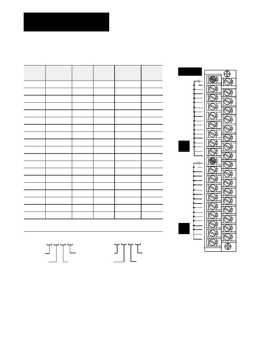
Table 3.C
1791ĆIOBW Output Terminal Addressing for Groups 0 and 1 (TRM2)
Terminal
Number
Output
Assignment
Group 1
Program
Address
Terminal
Number
Output
Assignment
Group 0
Program
Address
1
N.C.
20
Ground A
2
Ground B
21
Output 17
0XY17
3
Output 17
0X(Y+1)17
22
Output 16
0XY16
4
Output 16
0X(Y+1)16
23
Output 15
0XY15
5
Output 15
0X(Y+1)15
24
Output 14
0XY14
6
Output 14
0X(Y+1)14
25
Output 13
0XY13
7
Output 13
0X(Y+1)13
26
Output 12
0XY12
8
Output 12
0X(Y+1)12
27
Output 11
0XY11
9
Output 11
0X(Y+1)11
28
Output 10
0XY10
10
Output 10
0X(Y+1)10
29
Output 07
0XY07
11
Output 07
0X(Y+1)07
30
Output 06
0XY06
12
Output 06
0X(Y+1)06
31
Output 05
0XY05
13
Output 05
0X(Y+1)05
32
Output 04
0XY04
14
Output 04
0X(Y+1)04
33
Output 03
0XY03
15
Output 03
0X(Y+1)03
34
Output 02
0XY02
16
Output 02
0X(Y+1)02
35
Output 01
0XY01
17
Output 01
0X(Y+1)01
36
Output 00
0XY00
18
Output 00
0X(Y+1)00
37
VDC A
19
VDC B
Where:
X = Rack Number (1, 2, 3 ...)
Y = Module Group (0, 2, 4, 6)
Type of I/O
I/O Rack
Number
I/O Group
Number
I/O Bit
0 X Y 00
1 = Input
0 = Output
PLCĆ2 Example
Type of I/O
I/O Rack
Number
I/O Group
Number
I/O Bit
O X Y 00
I = Input
O = Output
PLCĆ3, PLCĆ5, PLC5/250 Example
NOTE: