Field descriptions – Rockwell Automation 1794-OE8H, Series B Flex I/O Output HART Module Installation Instructions User Manual
Page 24
24 FLEX I/O 8 Output HART Analog Module
Publication
1794-IN109D-EN-P - January 2014
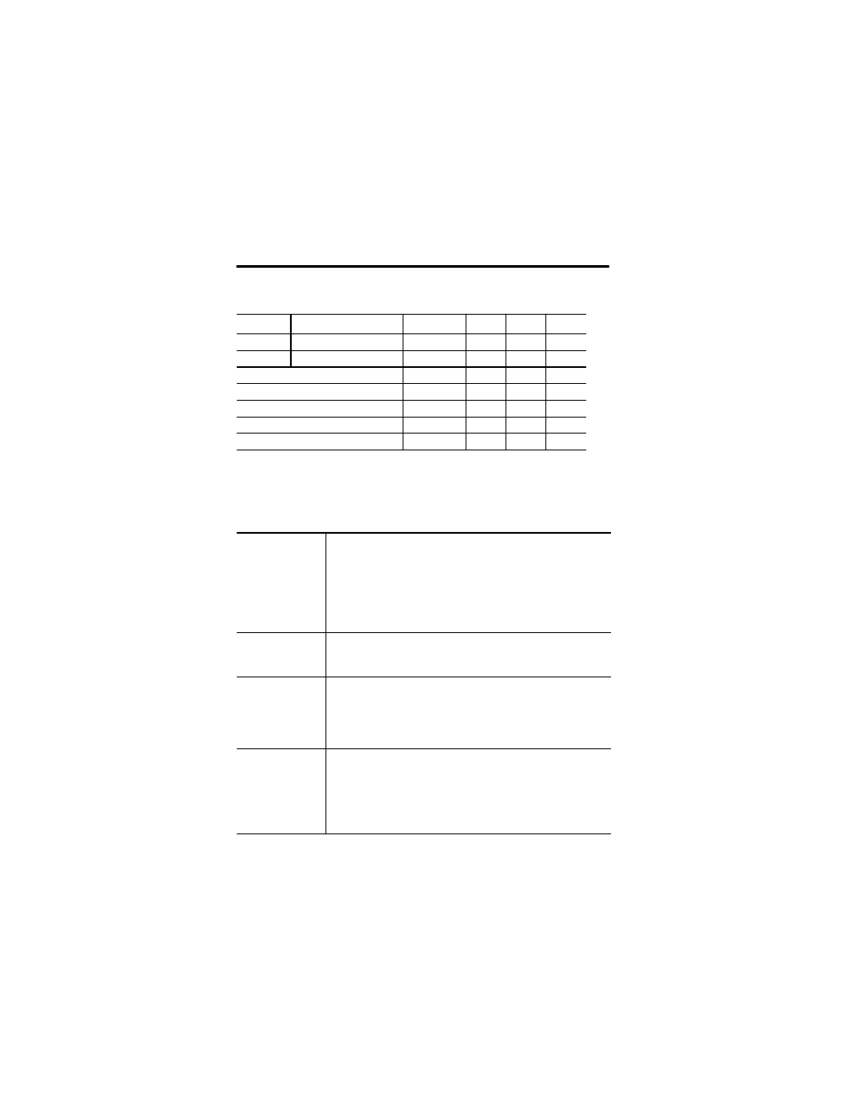
Secondary Master Enable (SME)/ Primary Master Inhibit (PMI)
(Series A Mode)
Bits
(1)
1 (Default)
2
3
4
PMI
8, 9, 10, 11, 12, 13, 14, 15 0
0
1
1
SME
0, 1, 2, 3, 4, 5, 6, 7
0
1
0
1
HART Smooth Fitler
Pulsed
On
Off
On
Rebuild
On
On
Off
Off
HART Read Back
On
On
Off
Off
Primary Master
On
On
Off
Off
Secondary Master
Off
On
Off
On
(1)
Where:
Ch 0 - bits 0 and 8; Ch 1 - bits 1 and 9; Ch 2 - bits 2 and 10; Ch 3 - bits 3 and 11; Ch 4 - bits 4 and
12; Ch 5 - bits 5 and 13; Ch 6 - bits 6 and 14; Ch 7 - bits 7 and 15
Field Descriptions
Analog/Digital
Output Mode
Selects if the channel acts as a normal analog output or as a switched
digital output.
Analog Output mode will follow the Analog Data Format selected.
Digital Output mode will output 0 mA = OFF, 22 mA = ON if the Fault
mode is 0 = disable. Digital Output mode will output 2 mA = OFF, 22
mA = ON if the Fault mode is 1 = wire off fault detection enabled.
Range: 0 = normal analog output, 1 = switched digital output.
Analog Output Data
Specifies the value of the analog output data to the module. Specific
format is controlled by Module Data Format Control parameter. This
data is used when the channel is in Analog Output mode.
Digital Output Data
Specifies the value of the digital output data to the module. This data
is used when the channel is in digital output mode.
Range: 0 = output, 0 mA = OFF, 1 = 22 mA = ON if the Fault mode is 0 =
disable. 0 = output, 2 mA = OFF, 1 = 22 mA = ON if the Fault mode is 1
= wire-off fault detection enabled.
Global Reset
This bit acts to reset all outputs to accept normal system output data.
It acts in conjunction with the Latch Retry parameter. If any channel
faults occur, the Latch Retry parameter can be set to cause the fault to
be latched and the output to go to its safe state value.
This is an edge-triggered signal. It must first be set (1). Reset will then
occur on the set-to-reset transition.