Choosing a slot in the chassis – Rockwell Automation 1746-XXXX SLC 500 4-Channel Analog I/O Modules Installation Instructions User Manual
Page 10
10 SLC™ 500 4-Channel Analog I/O Modules
Publication 1746-IN008C-EN-P - May 2004
Switch Settings for the 1746-NIO4I, -NIO4V, -FIO4I, and -FIO4V
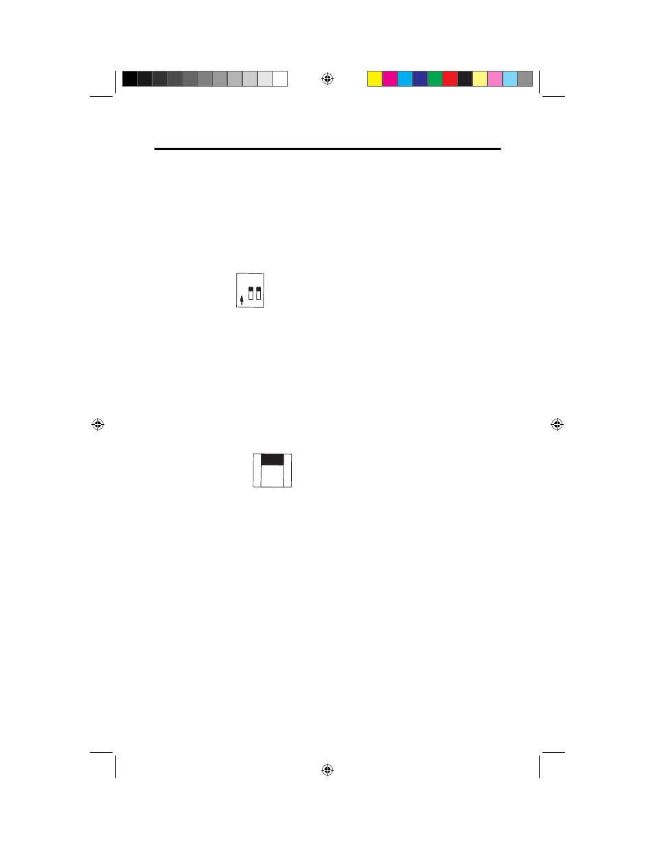
The NIO4I and NIO4V have 2 individual switches labeled 1 and 2. These switches
control the input mode of channel 0 and 1. A switch in the ON position configures
the channel for current input. A switch in the OFF position configures the channel
for voltage input.
External Power Switch for the 1746-NO4I and -NO4V
The NO4I and NO4V analog output modules have an external 24V dc power
switch, SW1, which gives you the option of using an external power supply. In the
UP position, power is drawn from an external power source. In the DOWN
position, power is drawn from the backplane of the module. The switch is located
on the analog module board. Switch orientation is also provided on the nameplate
of the module.
Choosing a Slot in the Chassis
Two factors determine where the analog module should be located in the chassis:
ambient temperature and electrical noise. Consider the following conditions when
selecting a slot for an analog module. Position the module:
•
in a slot away from an ac or high voltage dc modules
•
in the chassis closest to the bottom of the enclosure where the SLC 500
system is installed
•
away from the chassis power supply if installed in a modular system
Switch 1 = Channel 0
Switch 2 = Channel 1
1 2
N
O
Current
Voltage
External
Backplane
24V dc
Power
Selector
SW1
@JO$&/QQE
@JO$&/QQE
".
".