Rockwell Automation 1791-IOBB USER MANUAL User Manual
Page 9
Introducing Block I/O
Chapter 1
1Ć3
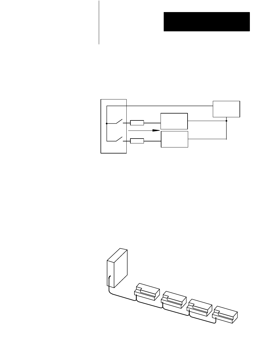
Sourcing outputs (Figure 1.3) have the power bussed in the block. When
the output is on, current is supplied to the field control device, which sinks
the current. The field circuit and the equipment remain at ground potential
until the output is turned on.
Figure 1.3
Sourcing Output Example
DC Power
Supply
Field
Device
Field
Device
+VDC
-V
Fuse
Fuse
10827-I
Block I/O
You connect the block I/O to your remote I/O link as you would any other
device (Figure 1.4). The block looks like a 1/4 I/O rack to the processor,
and uses 2 words of input image table memory and 2 words of output
image table memory. The block is addressed directly on the remote I/O
link.
Block I/O functions exactly like any Allen–Bradley remote I/O product.
Input and output data is scanned asynchronously and transferred back and
forth between the block and the controller input and output image table.
Figure 1.4
Block I/O Connection in a PLC System
Blocks are daisy-chained to
a programmable controller or a
scanner.
Block I/O - each block
is 1/4 I/O rack.
Programmable Controller or
Scanner.
10828-I