Installing the block i/o, Connecting wiring, Installing the block i/o connecting wiring – Rockwell Automation 1791-IOBB USER MANUAL User Manual
Page 12: Installing block i/o chapter 2
Installing Block I/O
Chapter 2
2Ć3
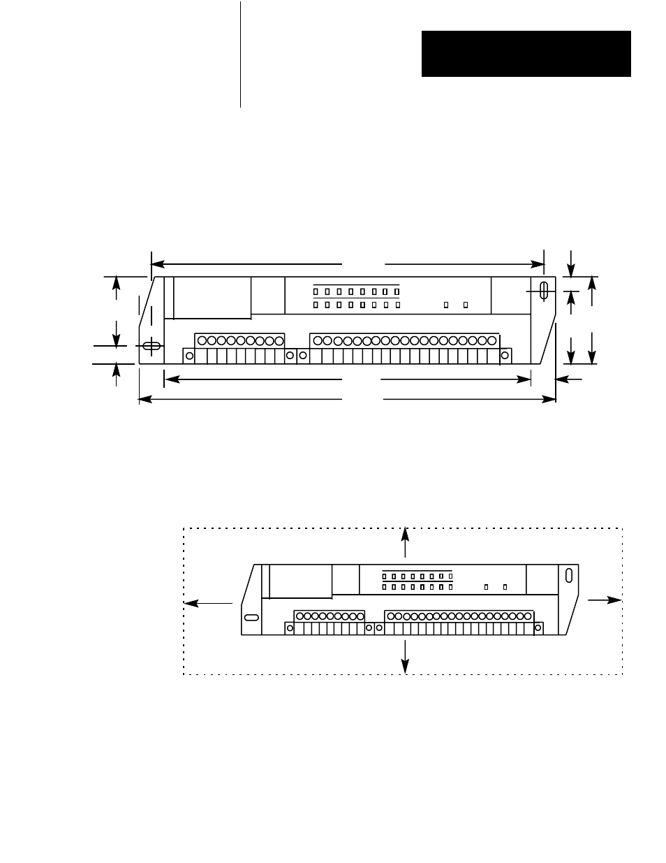
Figure 2.1 shows the mounting dimensions for the block I/O module.
Mount the blocks horizontally with a minimum of 2” between blocks. This
air gap is necessary to maintain proper cooling air flow through the block.
Figure 2.1
Mounting Dimensions for the Block I/O Module (Cat. No. 1791-IOBA/B
and -IOBB/B)
OUTPUT
INPUT
COMM POWER
180mm
7.1"
212mm
8.35"
35mm
1.37"
8mm
0.31"
10mm
0.39"
198mm
7.8"
10mm
0.39"
16mm
0.63"
16mm
0.63"
10829-I
Depth = 96.0mm (3.78")
The operating temperature in the air gap between block I/O modules must
not exceed 55
o
C (151
o
F). Figure 2.2 shows the dimensions of the required
air gap.
Figure 2.2
Clearance Required for Block I/O Modules
OUTPUT
INPUT
COMM POWER
51mm
2"
51mm
2"
51mm
2"
51mm
2"
10830-I
Connections to the block I/O module are made to the removable
connectors which plug into the front of the block. The connector blocks are
keyed to prevent incorrect insertion and are secured by screws.
Wiring for the block is shown in Figure 2.3 and Figure 2.4. Remote I/O
wiring connections are shown in Figure 2.5.
Installing the Block I/O
Connecting Wiring