Remove the finger-safe terminal block, Output wiring – Rockwell Automation 1769-HSC Compact High Speed Counter Module User Manual
Page 17
Compact I/O High-speed Counter Module 17
Publication 1769-IN030B-EN-P - October 2010
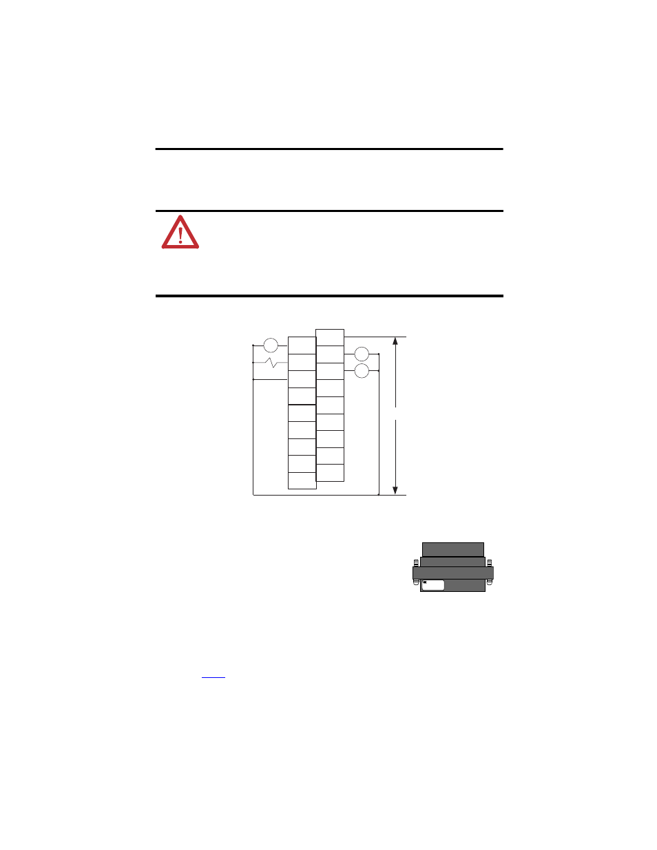
Output Wiring
Basic wiring
(1)
of output devices
(2)
to the module is shown in Figure 7.
Figure 7 - Output Device Wiring
Remove the Finger-safe Terminal Block
When wiring field devices to the module, it is not necessary to
remove the terminal block. If you remove the terminal block, use
the write-on label on the side of the terminal block to identify the
module slot location and type.
To remove the terminal block, loosen the upper and lower
retaining screws. The terminal block will back away from the module as you remove the screws.
When replacing the terminal block, torque the retaining screws to 0.46 N•m (4.1 lb•in).
ATTENTION: Follow these guidelines:
•
Miswiring of the module to an AC power source or applying reverse polarity
will damage the module.
•
Be careful when stripping wires. Wire fragments that fall into a module could
cause damage at powerup. Once wiring is complete, be sure that the module is
free of all metal fragments.
(1)
Recommended Surge Suppression - The module has built-in suppression which is sufficient for most applications, however,
for high-noise applications, use a 1N4004 diode reverse-wired across the load for transistor outputs switching 24V DC
inductive loads. For additional details, refer to Industrial Automation Wiring and Grounding Guidelines,
publication
.
(2)
Sourcing Output - Source describes the current flow between the I/O module and the field device. Sourcing output circuits
supply (source) current to sinking field devices. Field devices connected to the negative side (DC Common) of the field
power supply are sinking field devices. Field devices connected to the positive side (+V) of the field supply are sourcing field
devices. Europe: DC sinking input and sourcing output module circuits are the commonly used options.
CR
OUT 0
OUT DC
5/24 V DC
OUT 2
AO-
BO-
ZO-
A1-
B!-
Z1-
OUT
DC COM
OUT 1
OUT 3
AO+
BO+
ZO+
A1+
B1+
Z1+
CR
CR
5/24V DC
+DC
-DC
45200
SLOT # _____
MODULE TYPE ______