1 - introduction, Chapter objectives, Dio system overview – Rockwell Automation 1747-DSN DISTRIBUTED I/O SCANNER User Manual
Page 8: Introduction
A–B
1
Chapter
Introduction
This chapter contains the following information:
•
DIO system overview
•
DIO Link overview
•
DH–485 Data Link overview
•
how the scanner interacts with the SLC processor
•
scanner features
Important: Use the DIO scanner in any SLC 500 Modular Hardware
system. The scanner cannot be used in SLC 500 Fixed Hardware systems.
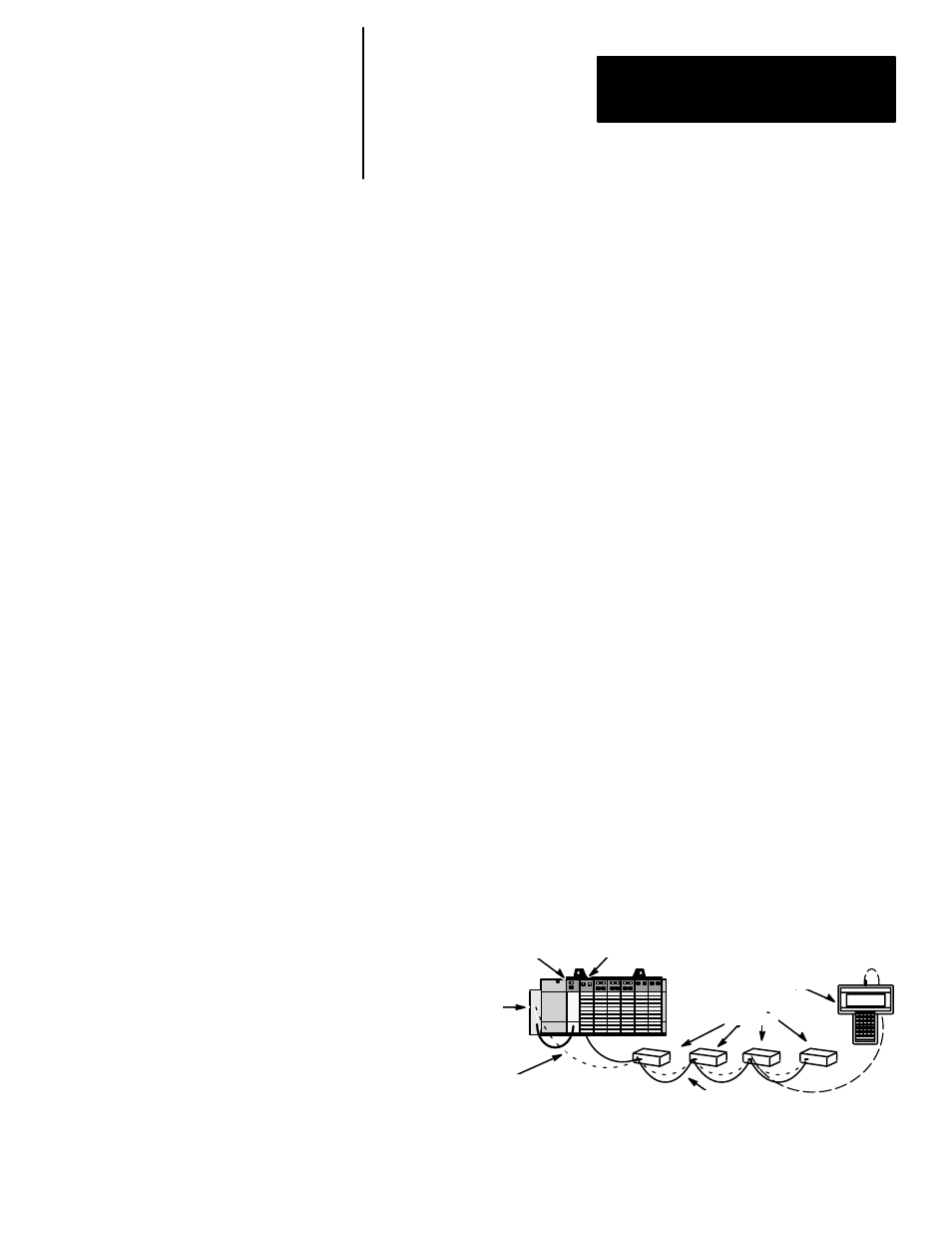
The DIO system consists of an SLC processor, a scanner, an Isolated Coupler
and I/O blocks. These devices form the DIO System when they are properly
connected to the DIO Link and the DH–485 Data Link as shown below. The
DIO Link and the DH–485 Data Link are independent networks.
The DIO Link consists of the scanner and I/O blocks. It enables the SLC
processor to exchange input and output information with up to 30 I/O blocks.
Output data is transferred from the SLC processor to the scanner, which then
transmits the data to the appropriate I/O block via the DIO Link. The
scanner receives input data from the I/O blocks via the DIO Link. The
scanner then provides this data to the SLC processor. The maximum length
of the DIO Link is 2,500 feet (762 meters) using Belden 9463 cable.
The SLC processor and programming devices communicate using the
DH–485 Data Link. The DH–485 port located on each I/O block allows
remote programming and/or monitoring of the SLC processor. It does not
directly control the I/O block.
Connecting a programming device to any I/O block programming port allows
the programming device to communicate with the SLC processor. The
maximum length of the DH–485 Data Link is 4,000 feet (1,219 meters) using
Belden 9842 cable.
DIO Link
Programming Device (HHT)
I/O blocks
SLC Processor
Scanner
Isolated Coupler
DH–485 Data Link
Chapter Objectives
DIO System Overview