Control word configuration information, 30 i/o block configuration output image example – Rockwell Automation 1747-DSN DISTRIBUTED I/O SCANNER User Manual
Page 27
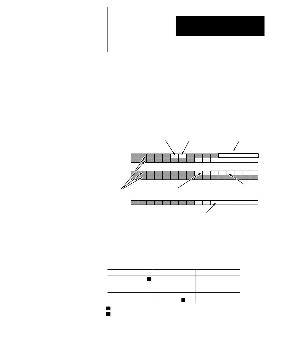
Input File
Control Word, Word 0
O:e.0
O:e.1
O:e.15
O:e.16
I/O block 1 (Output, Word 1)
I/O block 15 (Output Word 15)
Reserved, Word 16
0
1
2
3
4
5
6
7
8
9
10
11
12
13
14
15
Bit Number (decimal)
e = slot number of the SLC rack containing the scanner
Bits 6 and 7are only available to I/O
blocks with 8 outputs
Configuration Data Valid
bit 10
Disable Outputs
bit 9
Number of I/O
blocks bits 0 – 4
Reserved
The output word for each I/O block is placed in the word corresponding to the
I/O block address. The bits of each output word correspond to the outputs on
the I/O block. For example, bit 5 of output word 31 controls output 5 of I/O
block 31.
Control Word Configuration Information
1
1
2
2
00000 configures the scanner for 7 I/O blocks
Scanner detects rising edge
O:e.31
I/O block 31 (Output Word 31)
Output bits
Chapter 3
Configuration and Programming
3–9
Configuration Data Valid Bit – Bit 10 of the Control Word (word 0) must
be set after bits 0 –4 (Number of I/O blocks) are valid. When this bit is first
set to 1 (from run mode), bits 0 – 4 are used to configure the scanner with the
number of I/O blocks connected to the scanner.
Important: This bit should not be reset to 0 during program execution.
After this bit is set, further transitions of bits 0 – 4 (Number of I/O blocks)
are ignored.
30 I/O Block Configuration Output Image Example
Configurable Item
Values
Result
Number of I/O Blocks
00001 to 11110
1 – 30 I/O blocks
Disable Outputs
0
1
Outputs enabled
Outputs disabled
Configuration Data Valid
0
1
Invalid
Valid