Rockwell Automation 1747-DSN DISTRIBUTED I/O SCANNER User Manual
Page 17
Chapter 2
Wiring and Installation
2–5
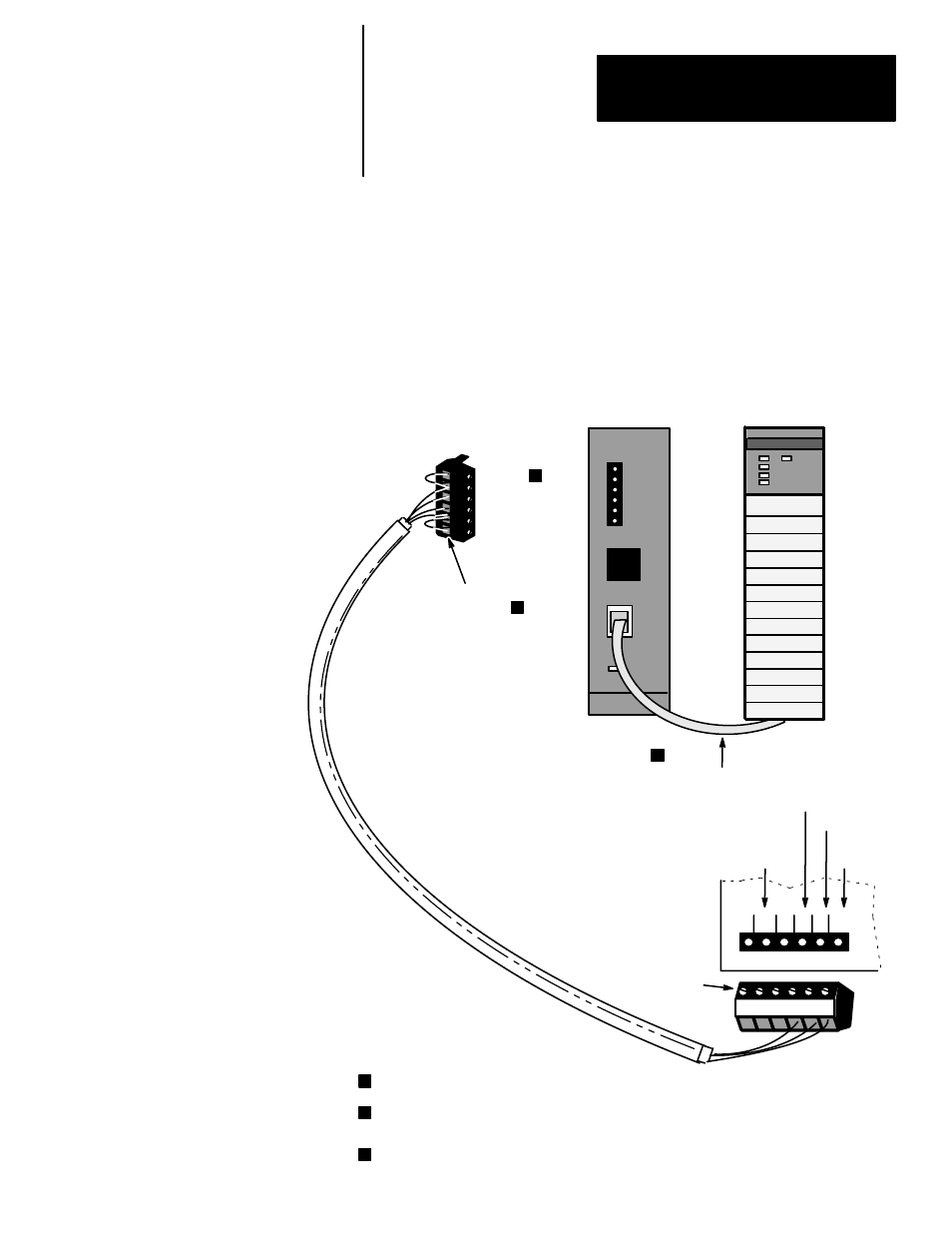
The Isolated Coupler is attached to the DH–485 Data Link using its 6
position DH–485 Data Link connector. The I/O blocks are attached to the
DIO Link using 4 of the 6 terminals on the DIO connector.
The DH–485 Data Link cable shield must be earth grounded at one point on
the link.
The SLC processor is connected to the Isolated Coupler with a Catalog
Number 1747–C11 Communication Cable, which is included with the
Isolated Coupler. The programming device is connected to the I/O block (or
Isolated Coupler) using a Catalog Number 1747–C10 Communication Cable.
A
2
1
SHD
A
2
COM
B
1
SHD
DH–485
Common
DH–485 B
DH–485 A
DIO / DH–485
shield
SLC CPU
Isolated Link
Coupler
SLC
Processor
Termination
DH–485 A
Common
Shield (drain wire)
Chassis Ground
DH–485 B
TERM
A
B
COMMON
SHLD
CHS GND
Chassis Grounding
Method 2
1
2
3
The wiring scheme shown is that of a 1747–AIC Series B Link Coupler. Although the Series A Link Coupler is
labeled differently, you do not have to rewire your connector.
Because the DIO/DH–485 shields are tied together at each block, you should only connect the shields to
chassis ground in one place. If you choose to ground the shields using Chassis Grounding Method 2, do not
use Chassis Grounding Method 1 (shown on page 2–3).
TERM and A must be jumpered (to terminate the link) if the Isolated Coupler is at the end of the DH–485 Link.
3
2
1
1747–C11
Communication
Cable
DIO Connector
for the I/O
block
B
COM