Scanner configurations, Scanner baud rate, I/o block addressing – Rockwell Automation 1747-DSN DISTRIBUTED I/O SCANNER User Manual
Page 12
Chapter 1
Introduction
1–5
The scanner can be configured for two different modes of operation. These
modes, or configurations, are referred to as 7 and 30 I/O block
configurations.
When the scanner is configured for a 7 I/O block configuration, the scanner
addresses up to seven I/O blocks. The SLC 5/01 and 5/02 processors support
the 7 I/O block configuration.
When the scanner is configured for a 30 I/O block configuration, the scanner
addresses up to 30 I/O blocks. The SLC 5/02 processor supports the 30 I/O
block configuration.
The scanner cannot be used with SLC 500 Fixed Hardware Systems.
Since the scanner operates at a fixed baud rate of 230.4K, configure the I/O
blocks for 230.4K baud. This lets the scanner communicate with the I/O
blocks.
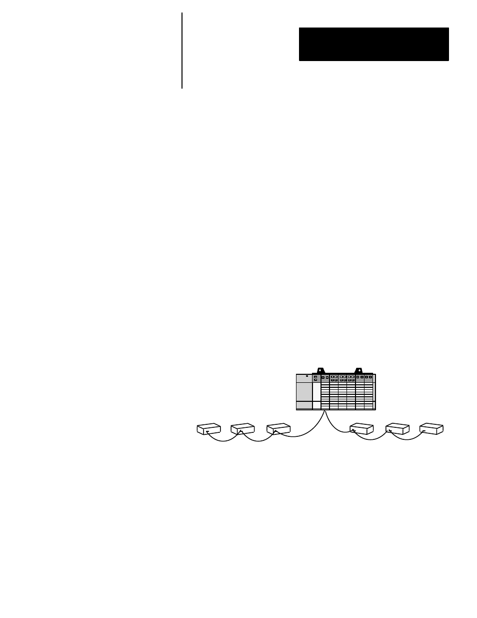
I/O blocks are addressed as I/O blocks 1 through 15 and 17 through 31.
There is no I/O block 16. I/O blocks must be addressed consecutively;
however, they do not have to be wired in a contiguous order.
I/O block
4
I/O block
1
I/O block
5
I/O block
6
I/O block
3
I/O block
2
In the example above, the six I/O blocks are addressed in numerical order
as I/O blocks 1 thru 6; however, they are not wired in numerical order.
A unique address is assigned to each I/O block using dip switches located on
each I/O block. These switches are also used to set the I/O block baud rate
and output Hold Last State operation. For further I/O block dip switch
information, see the I/O Block User’s manual, Publication 1701–6.5.1–DU1.
Scanner Configurations
Scanner Baud Rate
I/O Block Addressing