Rockwell Automation 1785-KA5P/B DHP COMM. ADAPATER MOD. User Manual
Page 44
Communicating through the 1785ĆKA5
Communication Adapter Module
Chapter 3
3-16
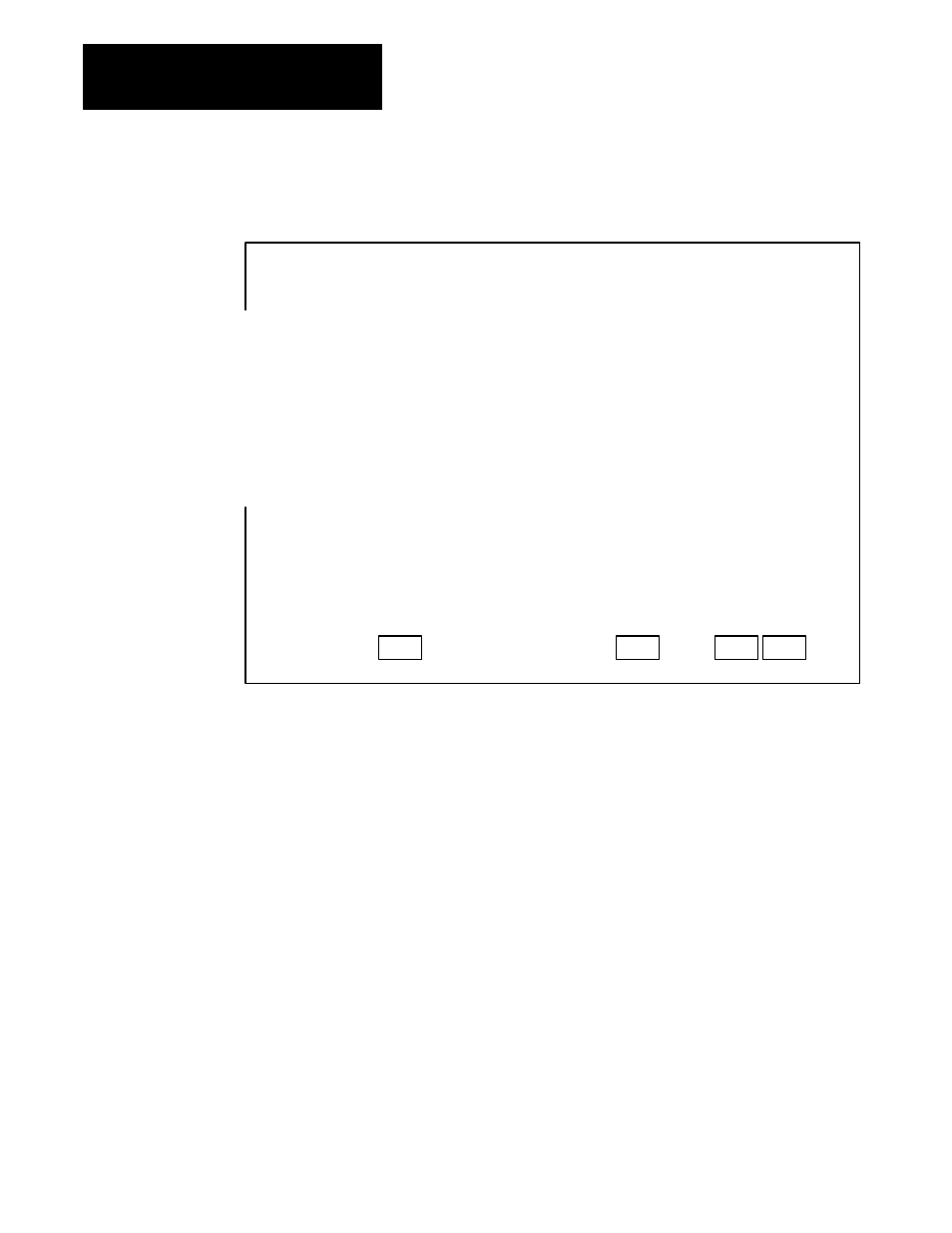
The monitor display screen allows you to monitor the status of the
message instruction while the processor is running:
Display Area:
Message:
Prompt:
Data/Cmd Entry:
Status:
Type:
Read/Write:
Target Device:
Channel:
F10
Target Node:
F1
Remote Bridge Link ID:
Remote Bridge Node Address:
Local Bridge Node Address:
Local/Remote:
Control Block:
Destination/Source File Address:
Target Offset
F6
Message Length in Elements:
Message Timeout (seconds):
F8
ERROR CODE:
Error Code Desc:
0
control bit address: N10 : 0/8
Peer-to-Peer
READ
485CIF
1
3
3
0
4
Remote
N10 : 0
N7 : 0
20
5
10
ignore if timed out:
continuous run:
error:
message done:
message transmitting
message enabled
to be retried:
awaiting execution:
waiting for queue space:
TO
CO
ER
DN
ST
EN
NR
EW
WQ
0
0
0
0
0
0
0
0
0
Press a function key:
offline
no forces
INSTR INSERT
File 009
Main Functions:
F1
F6
F8
F9
TARGET
NODE
TARGET
OFFSET
MESSAGE
TIMEOUT
TOGGLE
BIT
In this screen, the 5/03 processor reads 5 elements (words)
from Target node 3 or Remote Bridge LINK_ID 3, starting at
byte offset 20 of its PLC 3 compatibility file. This is a byte
offset because the device at node 3 is a PLC-5/40.
The 5 elements are placed in the integer file starting at
error bit N10:0/12 will be set, indicating that the
instruction timed out. The device at node 3 of the
Remote Bridge LINK_ID 2 understands the
485CIF (PLC 2 emulation) protocol.
word N7:0. If 10 seconds elapse without a reply,