Rockwell Automation 1785-KA5P/B DHP COMM. ADAPATER MOD. User Manual
Page 39
Communicating through the 1785ĆKA5
Communication Adapter Module
Chapter 3
3-11
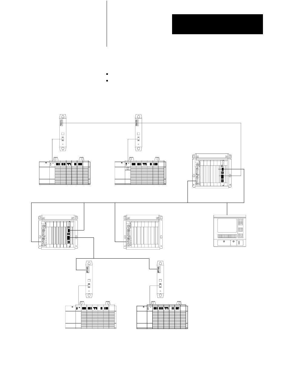
The next sections describe two types of remote messaging. Refer to
Figure 3.3 with the following examples:
remote read from a 500CPU
remote read from a 485CIF
Figure 3.3
Connections for a remote message.
1747-AIC
1747-AIC
DH - 485 network
DH - 485
network
SLC 5/03
SLC 5/02
PLC-5 processor with
a 1785-KA5 module
Node 1
Data Highway Plus network
Node 2
PLC-5 processor with
a 1785-KA5 module
LINK_ID = 1
LINK_ID = 3
Node 2
Node 3
LINK_ID = #
Node 1
SLC 5/02
SLC 5/02
1747-AIC
1747-AIC
Node 6 is the orginating node of MSG
instruction. (You do not need to specify
its address.)
Node 4 is the Local Bridge
node address.
Node 7 is the remote node address of
the local bridge. (You do not need to
specify its address.)
STATION 8 is the Remote
Bridge Address.
Node 5 is the remote node address
of the remote bridge.
Node 3 is the Target station address.
Link ID = 2 is the Remote Link_ID
DH - 485 network
DH - 485
network
DH - 485
network
DH - 485
network
DH - 485 network
Node 9
(11 octal)
20096
Node 6
Node 8
Node 5
LINK_ID = 2
Node 3
Node 4
Node 7
T60 Workstation
PLCĆ5/40 processor