I/o memory mapping, Input data file – Rockwell Automation 1769-IF8 Compact 1769-IF8 Analog Input Module User Manual
Page 13
Compact I/O 1769-IF8 Analog Input Module 13
Publication 1769-IN067B-EN-P - September 2005
I/O Memory Mapping
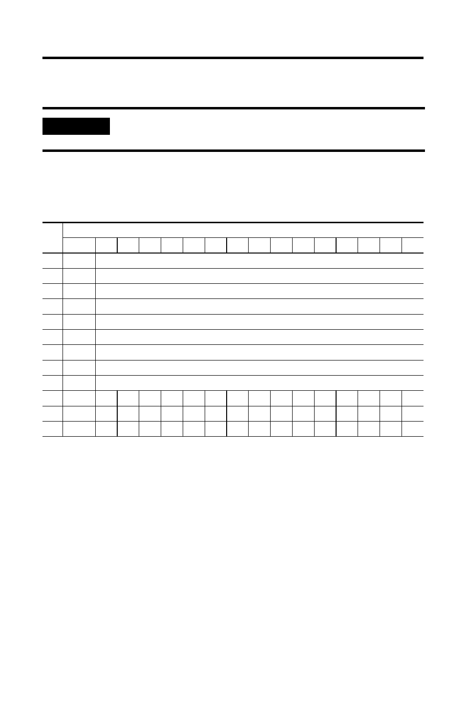
Input Data File
For each input module, slot x, words 0-7 in the input data file contain the analog
values of the inputs.
The bits are defined as follows:
• SGN = Sign bit in two’s complement format
• Nu = Not used. Bit set to 0.
• Sx = General status bit for input channels 0 through 7.
• Lx = Low alarm flag bits for input channels 0 through 7.
• Hx = High alarm flag bits for input channels 0 through 7.
• Ux = Under-range flag bits for channels 0 through 7. When set, the input
signal is under normal range or an open circuit condition exists, in the case
of the 4-20 mA range.
• Ox = Over-range flag bits for channels 0 through 7.
IMPORTANT
If you are using RSLogix 5000, version 15, please refer to RSLogix
5000, Version 15, Controller Tags on page 18.
Wo
rd
Bit Position
15
14
13
12
11
10
9
8
7
6
5
4
3
2
1
0
0
SGN
Analog Input Data Channel 0
1
SGN
Analog Input Data Channel 1
2
SGN
Analog Input Data Channel 2
3
SGN
Analog Input Data Channel 3
4
SGN
Analog Input Data Channel 4
5
SGN
Analog Input Data Channel 5
6
SGN
Analog Input Data Channel 6
7
SGN
Analog Input Data Channel 7
8
Nu
Time Stamp Value
9
Nu
Nu Nu
Nu
Nu
Nu
Nu
Nu
S7
S6
S5
S4
S3
S2
S1
S0
10
L3
H3 U3
O3
L2
H2
U2
O2
L1
H1
U1
O1
L0
H0
U0
O0
11
L7
H7 U7
O7
L6
H6
U6
O6
L5
H5
U5
O5
L4
H4
U4
O4