Rockwell Automation 1404-M4_M5_M6_M8 Powermonitor 3000 Master Module Installation Instructions User Manual
Page 43
Powermonitor 3000 Master Module 43
Publication 1404-IN007F-EN-P - November 2009
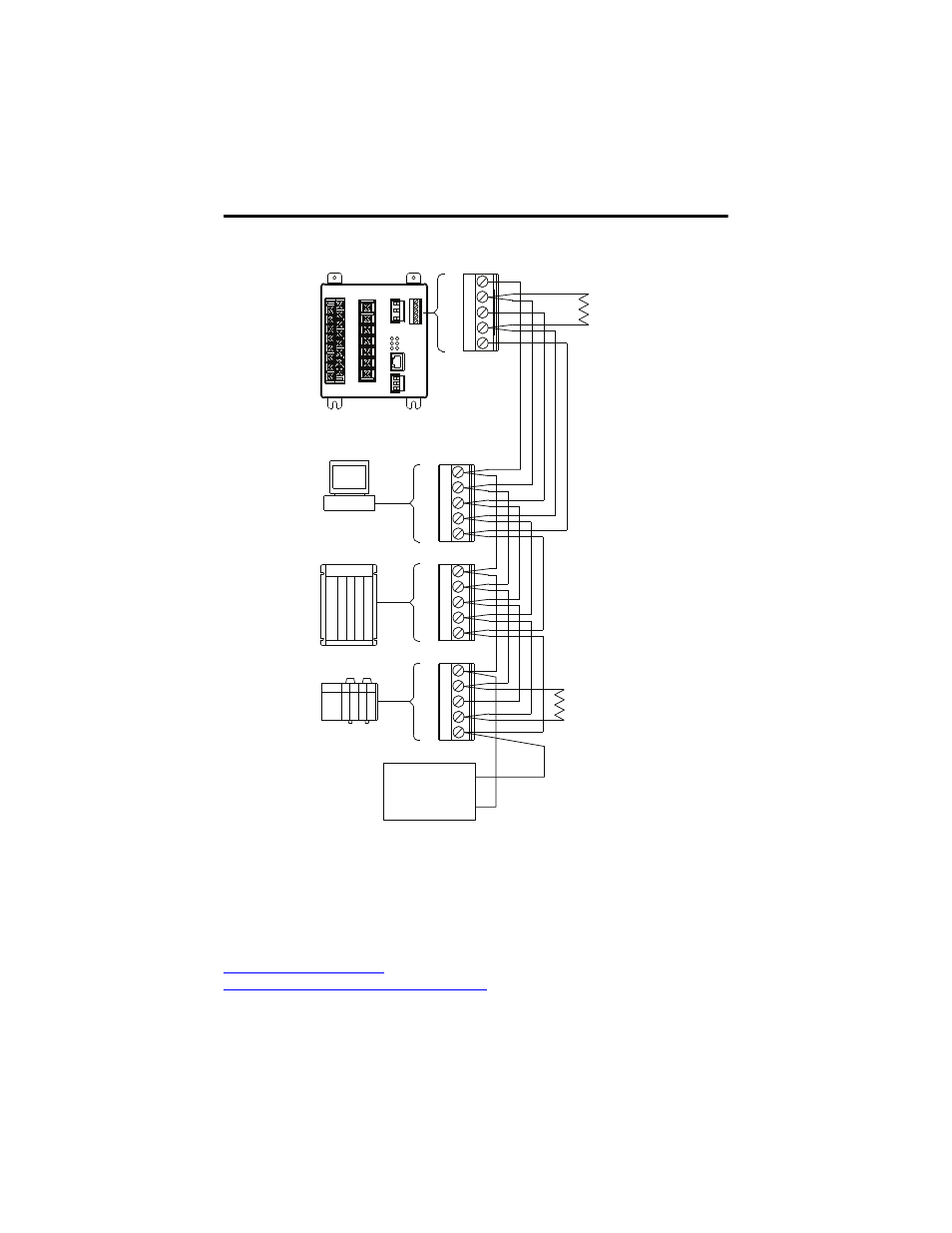
Connecting Powermonitor 3000 to Other DeviceNet Devices
Optional Ethernet Communication
Powermonitor 3000 units with catalog numbers ending in -ENT are equipped with an
industry standard Ethernet 10/100baseT port.
The power monitor is designed to connect easily to industry-standard Ethernet hubs and
switches using standard UTP (unshielded twisted-pair) cables with RJ-45 connectors. The
table shows the cable and connector pin assignments and
Powermonitor 3000 Ethernet Network Example
shows a typical star network topology.
121
Ω
Terminating
Resistor
(See Note 2)
121
Ω
Terminating
Resistor
(See Note 2)
IBM Compatible Personal Computer With
1784 PCDPCMCIA Interface Card
Or
1770-KFD Interface Box
Or
PLC With
1771-SDN Scanner
Or
SLC With
1747-SDN Scanner
Notes:
1) Example network protrayed.
For detailed DeviceNet
installations,
including
cable requirements, refer to
the DeviceNet Cable System
Planning and Installation Manual,
publication
DNET-UM072.
2) Terminating Resistors
must be connected
to each end of the
DeviceNet network. Omit the
terminating
resistors
if the devices already
are equipped with internal
terminating
resistors.
Powermonitor 3000 Device
V-
V+
CAN_L
SHLD
CAN_H
V-
V+
CAN_L
SHLD
CAN_H
V-
V+
CAN_L
SHLD
CAN_H
V-
V+
CAN_L
SHLD
CAN_H
+
-
DeviceNet
24V DC
Power Supply
Or Other DeviceNet
Scanner Devices