Front side and user elements, Terminals and wiring – Rockwell Automation 1606-XLP50E Power Supply Reference Manual User Manual
Page 10
All parameters are specified at 24V, 2.1A, 230Vac input, 25ªC ambient and after a 5 minutes run-in time unless noted otherwise.
10
Rockwell Automation Publication 1606-RM034A-EN-P — March 2014
Bulletin 1606 Switched Mode Power Supplies
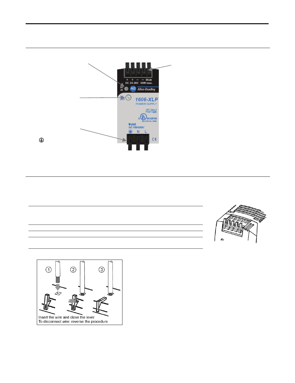
14. Front Side and User Elements
Fig. 14-1 Front side
DC-OK
LED (green)
On when the voltage at the
output terminals is > 20 V
DC-OK LED and DC-OK signal
functions are synchronized
Output Voltage
Potentiometer
Turn to set the output voltage.
Factory set: 24.5V
Input Terminals
Spring-clamp terminals
N
… Neutral input
L
… Line (hot) input
... PE (Protective Earth) input
Output & Signal Terminals
Spring-clamp terminals
Dual terminals per pole
+
Positive output
-
Negative (return) output
Dual pins per pole
DC-OK
Open collector output
Indicates an output
voltage higher than
20Vdc
15. Terminals and Wiring
All terminals are easy to access when mounted on the panel. Input and output terminals are separated from each
other (input below, output above) to help in error-free wiring. Mounting and wiring do not require a screwdriver.
s
l
a
n
i
m
r
e
t
p
m
a
l
c
-
g
n
i
r
p
s
t
c
e
n
n
o
c
-
k
c
i
u
Q
e
p
y
T
m
m
4
-
3
.
0
e
r
i
w
d
i
l
o
S
2
m
m
5
.
2
-
3
.
0
e
r
i
w
d
e
d
n
a
r
t
S
2
American wire gauge 26-12 AWG
d
e
r
i
u
q
e
r
t
o
n
t
u
b
,
d
e
w
o
l
l
A
s
e
l
u
r
r
e
F
Wire stripping length 6mm / 0.25inch
N
0
4
:
G
W
A
6
1
,
N
0
5
:
G
W
A
4
1
,
N
0
6
:
G
W
A
2
1
e
c
r
o
f
t
u
o
-
l
l
u
P
(according to UL486E)
Fig. 15-1 Connecting a wire
Instructions:
a)
Use appropriate copper cables
b)
Follow local and national installation codes and
regulations!
c)
Ensure that all strands of a stranded wire enter
the terminal connection!
d)
Do not use the unit without PE connection.