Notice, Disconnect switch location and installation, Single phase ac three phase ac direct current – Rockwell Automation 1494U-D30_D60_D100 Universal Disconnect Switch Installation Instructions (30A, 60A, 100A) User Manual
Page 2: Ho le use d fo r step 2, Install disconnect switch, Install line terminal guard, L1 l2 l3
PN-224754
DIR 10001182729 (Version 01)
When locating the 30A, 60A and 100A cable operated switch, verify that the minimum diameter for the loop of the cable
between the switch mechanism and handle mechanism is not less than 6 inches.
NOTICE
Any reduction to the diameter of the bend loop for the cable will reduce the efficiency of the cable system, create additional drag and friction within
the cable conduit and possibly decrease system life.
1
Measure top hole of handle on enclosure.
Measure hole center to side of enclosure: _______
Measure hole center to top of enclosure: _______
Switch Moun
ting Holes
Ce
nt
er punch and drill (4) 11/64" holes
for th
read
forming
(T
AP
-TITE) sc
re
ws
p
ro
vided with switch
Variable Depth Dis
conne
ct
Switch
Hole
Lo
ca
tion
Templ
ate (30A - 60A - 100
A)
4-
7/
8
1-
13
/16
2-
7/
8
1-
3/
4
PN-
25496
9
DIR
100
01
12
03
59
(Vers
ion
00
)
Co
py
rig
ht
©
20
14
Ro
ckw
ell
Au
toma
tion
, Inc.
Al
l R
ight
s Reserved
. Printe
d i
n U
SA
.
St
ep 1
: M
ea
sure
top h
ol
e
of
h
an
dl
e o
n
en
clos
ur
e
· Measur
e h
ol
e c
ent
er to
sid
e o
f e
nc
losur
e
· Measur
e h
ole cent
er to
to
p
of
enc
losu
re
St
ep 2
: L
ay
te
mpl
at
e on
enc
losure b
ack
pl
ate
an
d
alig
n b
y u
sing
th
e
top h
ol
e on
p
aper a
nd
mea
sure
m
ents taken
from
St
ep
1
St
ep 3
: Tap
e t
empl
ate
do
wn
, pu
nc
h,
and
dril
l
hol
es
Ho
le
use
d
fo
r Step
2
2
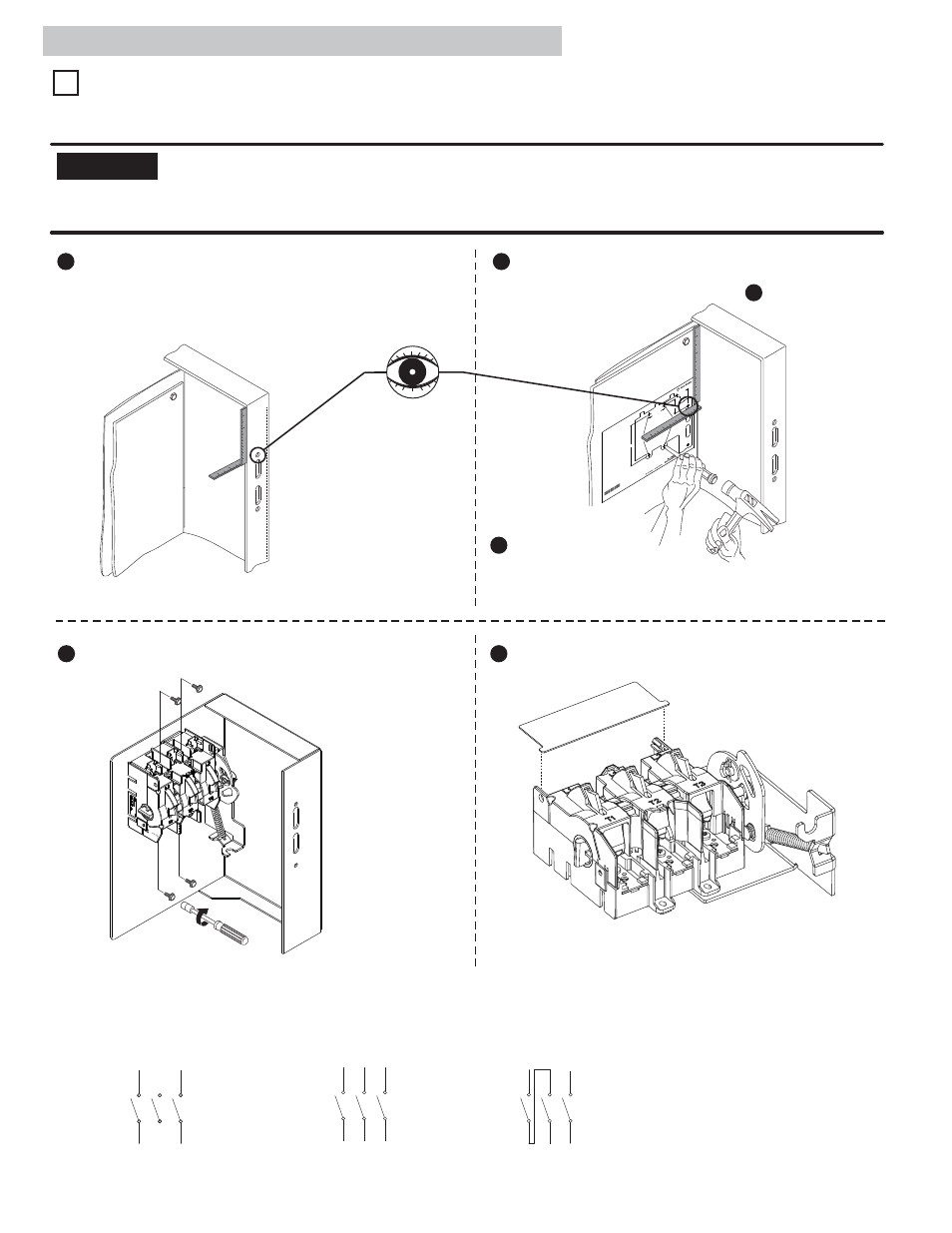
Use template PN-254969 to locate handle holes on mounting plate.
Lay template on enclosure back plate. Align using the top hole on
paper and measurements taken from step .
1
3
Tape template down.
Center punch and drill (4)
11/64” holes for thread
forming (TAP-TITE) screws
provided with switch.
4
Install Disconnect Switch.
5
Install Line Terminal Guard.
23 - 37 lb-in
7/16” Nut Driver
Disconnect Switch Location and Installation
A) For Rod Operated Switches, follow steps 1 - 5 below.
B) For Cable Operated Switches, follow steps 3 - 5 below.
1
Rod and Cable Operated Disconnect Switch Location
Wiring Diagrams
Single Phase AC
Three Phase AC
Direct Current
L1 L2 L3
L1 L2 L3
T1 T2 T3
T1 T2 T3
T1 T2 T3
L1 L2 L3
(2)