Sls test procedure – Rockwell Automation 1000 Safety Lockout System User Manual
Page 27
Publication 1000-UM001B-US-P - July 2000
Troubleshooting Guide 5-3
SLS Test Procedure
If an SLS box needs to be removed from the main control panel, it can be
tested as follows.
Wiring diagram:
Y-155798 Rev. M = SLS box
Y-156328 Rev. B = SLS switch
Y-156386 Rev. B = test procedure control panel
In addition to the normal Allen-Bradley test procedure, the following should
also be done:
1. Connect test control panel per Y-156386 Rev. B at PLC connector and
power test panel with 24V DC separate control.
2. Connect four SLS switches wired per Y-156328 Rev. B.
3. Apply 480V or 400V three-phase to line side of isolation contactor.
4. Turn the four SLS switches to ON position.
5. Energize 1SR with selector switch on test control panel.
6. Observe all LEDs in SLS box for condition. Observe pilot lights on test
control panel for condition. SR, 1SR, IC, and 1CR should be energized.
7. All SLS switch SAFE lights should be off.
8. Measure DC voltage on power supply output. If necessary, adjust to
27V.
9. Check voltage on secondary of CCT.
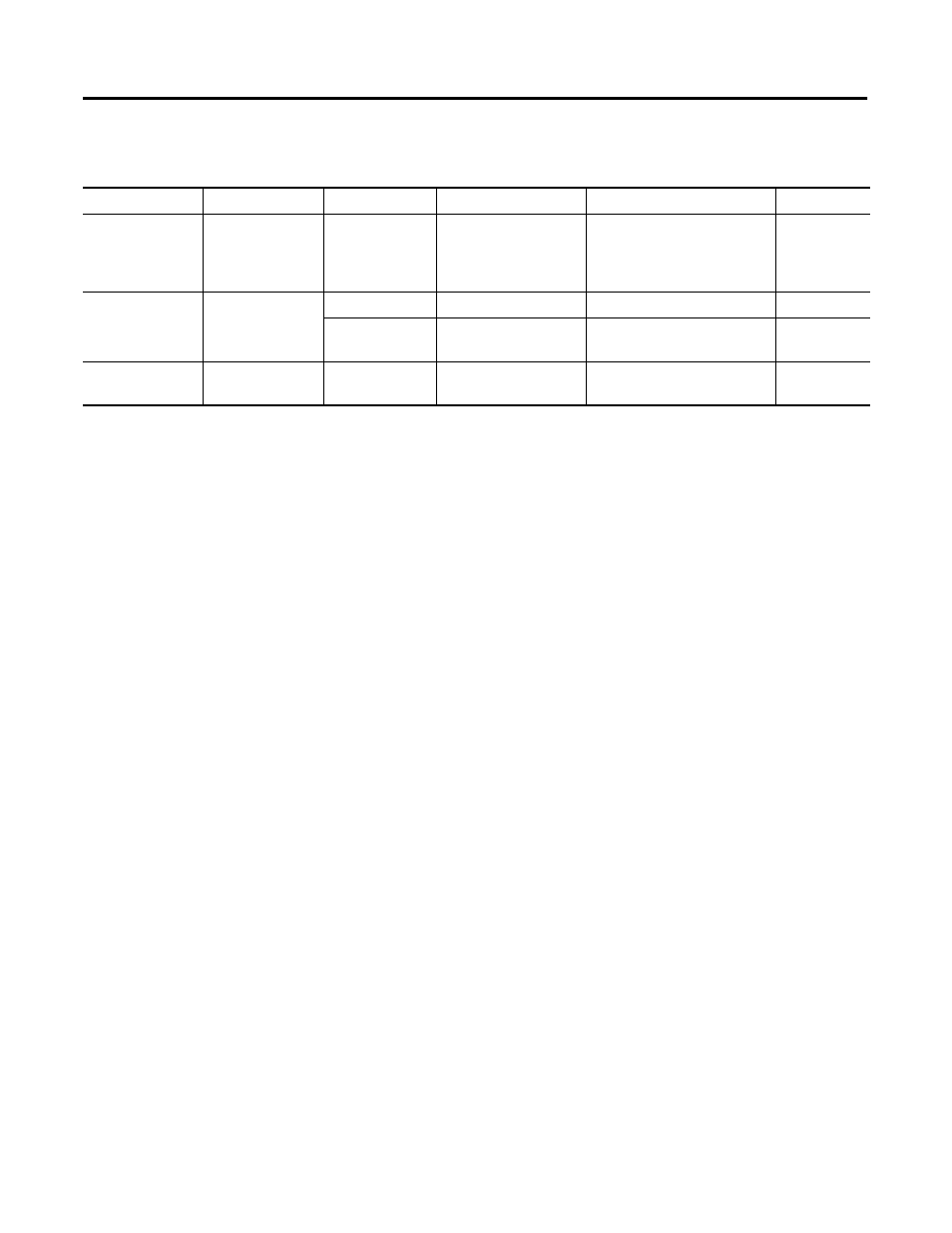
Table 5.B SLS Switch
Problem
Component
Possible Cause
Check
Suggested Action
Repairable?
Does not
illuminate with all
other circuitry
checking OK
Pilot light
Burned out bulb
Loose
connections
Connections
Replace bulb.
Tighten connections.
Yes
Contacts do not
operate properly
SLS switch
Bad switch
Continuity and operation Replace.
No
Handle
mechanism
For operation
Replace.
No
Contacts do not
operate properly
SLS switch
auxiliary contact
Bad contact
Continuity and operation Replace.
No