Rockwell Automation 1000 Safety Lockout System User Manual
Page 14
Publication 1000-UM001B-US-P - July 2000
1-2 Installation Instructions
Note: If the Class J fuses protecting the SLS box are smaller than that
specified, the equipment grounding conductor may be reduced to that as
shown in Table 250-95 of the NEC.
E. This SLS box has Harting connectors for four SLS switches with safe
light (Cat. No. 1000-NXSLS). If less than that four are needed for an
installation, jumper out the unneeded SLS switches in the male end of
the Harting connector. Refer to wiring diagram Y-155798.
Example: If SLS #4 is not needed, remove the hood on the male
Harting SLS connector and install a jumper between pins #3 and #8 on
the insert and install another jumper between pins #4 and #9 on the
insert. This will jumper out the missing SLS switch #4. Re-install the
hood and clamp the male Harting connector back in the SLS #4
position.
F. If an installation requires more than four SLS switches, an expansion
box(es) can be installed to increase the total number of SLS switches.
Refer to drawings Y-156773 and Y-157131.
G. The SLS enclosure must be bolted to the mounting plate of an enclosure
in the vertical position. Refer to drawing YD-24475 for mounting
dimensions.
H. The SLS box must be protected upstream from the isolation contactor
by a Class J time delay fuse. Maximum available fault current is 42 KA at
480V. In order to ensure IEC 947-4-1 Type 2 or better protection, fuses
are to be sized per NEC Article 430 part D, but shall not exceed the
following:
85 A contactor size = 100 A max.
30 A contactor size = 30 A max.
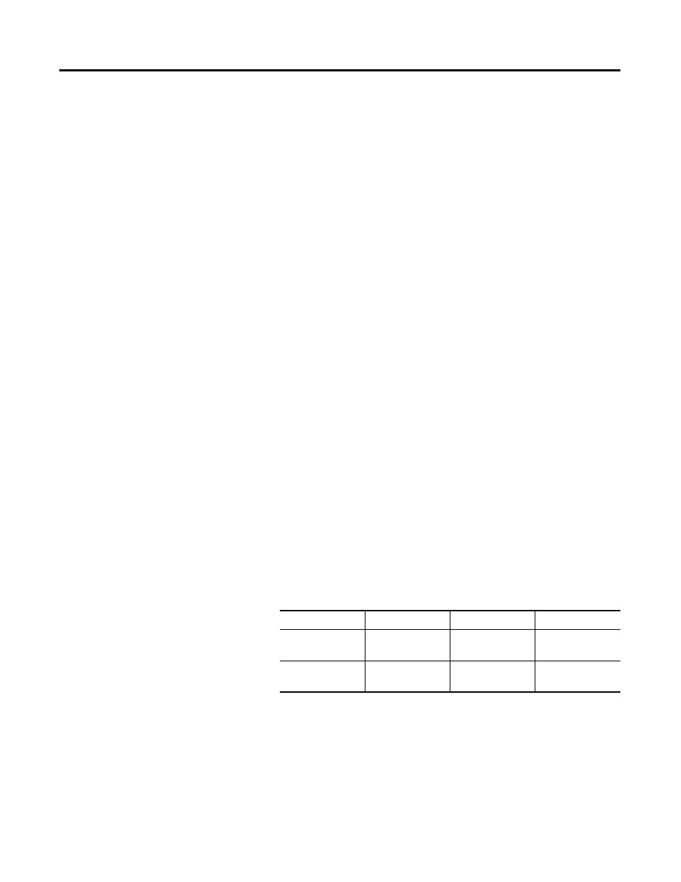
I. Power wire size and terminal torque
J. SLS switch installation
1. Mount in the vertical plane per drawing YD-24492.
2. Use conduit and hub or strain relief cord grip.
3. Connect SLS cable to terminal blocks that correspond to the pin
numbers on the Harting connectors per drawing Y-156328.
Table 1.A
SLS Rating
Cat. No.
Power Wire Size Terminal Torque
30 A with Pilz relay 1000-NXSLSV30
#14…#6 AWG
(2.5…16 mm
2
)
31 lb-in. (3.5 Nm)
+0%…5%
85 A with Pilz relay 1000-NXSLSV85
#14…#2 AWG
(2.5…50 mm
2
)
52 lb-in. (6 Nm)
+0%…5%