Rockwell Automation 1391ES AC Servo Controller User Manual
Page 26
Description of Operation
Chapter 4
4-24
Power-Up/Down Sequence
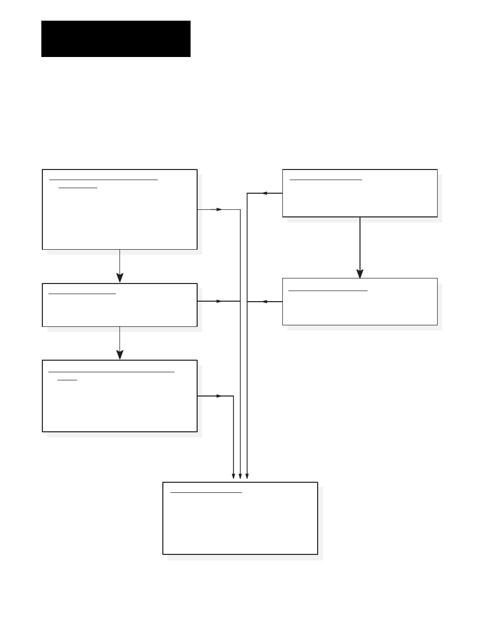
Figure 4.4 describes the various steps involved in the power-up/down
sequence of the 1391B-ES controller.
Figure 4.4
Controller Power-Up / Down Sequence
Application of 240V AC to Isolation
Transformer
a) Logic power supplies and base drive circuits
power-up.
b) Apply 115V AC to contactor.
c) Power bus charges.
d) If no faults are encountered, the DROK relay
energizes. Controller is ready to receive
customer enable signal.
Enable Signal is Applied Prior to 36V AC
Power
a) When 36V AC power is applied, fault circuits
detect that the enable signal is already applied.
Random fault conditions occur.
b) Re-application of enable after resetting the
controller and with 36V AC power still
present, will energize the controller.
Enable Signal Removed
a) Motor will regenerate to a stop.
b) Output power stage is disabled.
c) DROK relay maintains a no fault status.
Fault Condition Occurs
a) Controller output stage disabled.
b) DROK relay is de-energized and a fault is
latched.
c) If contactor is wired to the DROK relay in a
stop string, contactor will open and the shunt
regulator will discharge the power bus
supply.
POWER-UP
SEQUENCE
240V AC Power Removed
a) Logic and DC link power supplies begin
decaying to zero volts.
b) Undervoltage (fault) condition occurs.
POWER-DOWN
SEQUENCE
Enable Signal Applied
Minimum of 100 ms after Contactor is Closed
a) Base drive enabled and will respond to
customer command inputs.
Fault
Fault
Fault
Fault
Fault