Post installation (testing) – Rockwell Automation 1500 Modular Protection System Conversion Kit (GE Multilin to Bulletin 825 Plus) User Manual
Page 24
1500-IN059C-EN-E – June 2013
4-10
Installation
Post Installation (Testing)
Failure to follow these steps can result in damage to
equipment and/or personal injury.
1. Inspect the interior of the enclosure for contamination, loose bolts,
tools or metal chips, and vacuuming the enclosure is recommended.
2. Account for all the tools used. If a tool or hardware is unaccounted for,
do not energize the equipment.
3. Inspect the wiring and the control scheme to ensure proper operation.
Extra care should be taken when inspecting the connections for the cur-
rent transformer and ground fault circuits, to ensure neither circuits are
open or short-circuited during power-up.
4. For medium voltage controllers, follow items 5 though 7. For other
styles of controllers, the intent of this section is to apply control voltage
to the controller circuit, including the 825 Plus.
5. The medium voltage non-load break isolation switch must be in the
fully opened position (the isolation switch handle moved to the OFF/
down position).
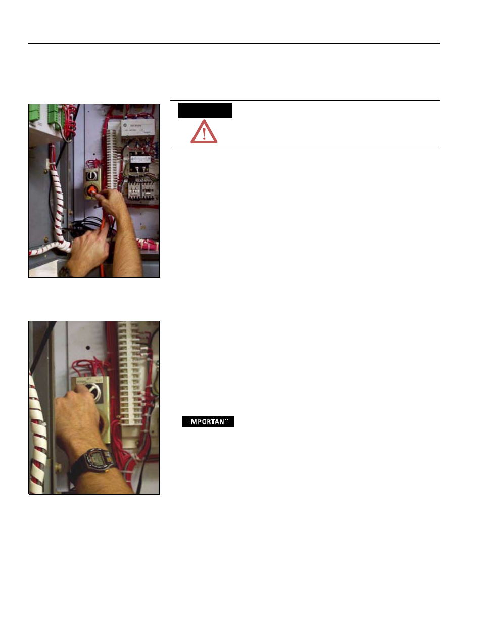
6. Connect a remote 120VAC external power source to the ‘NORMAL-
OFF-TEST’ (N-O-T) switch assembly test receptacle located in the low
voltage compartment. (Figures 4.28 and 4.29)
7. Turn the N-O-T selector switch to the TEST position. (Figure 4.29)
With the selector switch in the test position, power will
be applied to the control circuit. Additional caution must
be taken to prevent accidental contact with the 120VAC.
Figure 4.8
Figure 4.9
ATTENTION
IMPORTANT