Disconnect switch installation (cont'd), Disconnect handle installation, Cable mechanism installation – Rockwell Automation 1494C-xxx - Series 2 Cable Operated Disconnect Switch Kit and Acessories (600A) User Manual
Page 4
90 - 130 lb-in
(4)
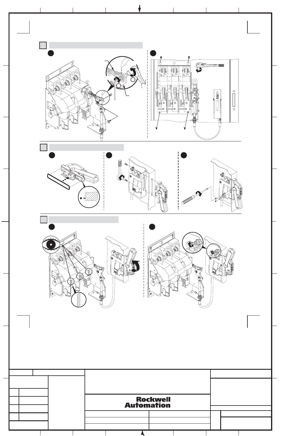
Disconnect Switch Installation (Cont'd)
(4) - 5/16-18 thread
forming screws
provided with
disconnect switch.
7
1
Assemble disconnect switch assembly to mounting plate.
6
Attach threaded rod to cable mechanism lever.
BULLETIN 1494C (600A) CABLE OPERATED
DISCONNECT SWITCH KIT INSTALLATION
INSTRUCTION SHEET
1
1026760
42052-190
OF
N/A
N/A
N/A
REVISION
AUTHORIZATION
DR.
CHKD.
APPD.
DATE
DATE
DATE
E - DOC
LOCATION: MILWAUKEE, WISCONSIN U.S.A.
B-vertical.ai
DWG.
SIZE
SHEET
B
1
2
3
4
5
6
7
8
A
B
C
D
E
F
G
H
REFERENCE
DIMENSIONS APPLY BEFORE
SURFACE TREATMENT
(DIMENSIONS IN INCHES)
TOLERANCES UNLESS
OTHERWISE SPECIFIED
.XX:
.XXX:
ANGLES:
42052
-------------
-------------
-------------
-------------
-------------
-------------
THIS DRAWING IS THE PROPERTY OF
ROCKWELL AUTOMATION, INC.
OR ITS SUBSIDIARIES AND MAY NOT BE COPIED,
USED OR DISCLOSED FOR ANY PURPOSE
EXCEPT AS AUTHORIZED IN WRITING BY
ROCKWELL AUTOMATION, INC.
4
13
Cable Mechanism Installation
3
NOTE: Apply grease from
capsule to gasket or groove
to retain gasket to handle.
Disconnect Handle Installation
Install gasket.
1
2
3
2
7-11 lb-in
Install handle and mechanism bracket.
Install defeater lever.
(Right Hand
Flange Mounted
Shown)
60 - 80 lb-in
1
Verify that disconnect switch and handle are in the "ON"
position.
2
Rotate connecting rod (clockwise) into drive bar until it
begins to exit the drive bar (approximately 18 full turns).
1
2
Threaded
Rod
Cable
Mechanism
Lever
90 - 130 lb-in
90 - 130 lb-in
C
L
O
S
E
D