Rockwell Automation 1400-SP PowerMonitor Software User Manual
Page 19
Chapter 3
Installation
3–5
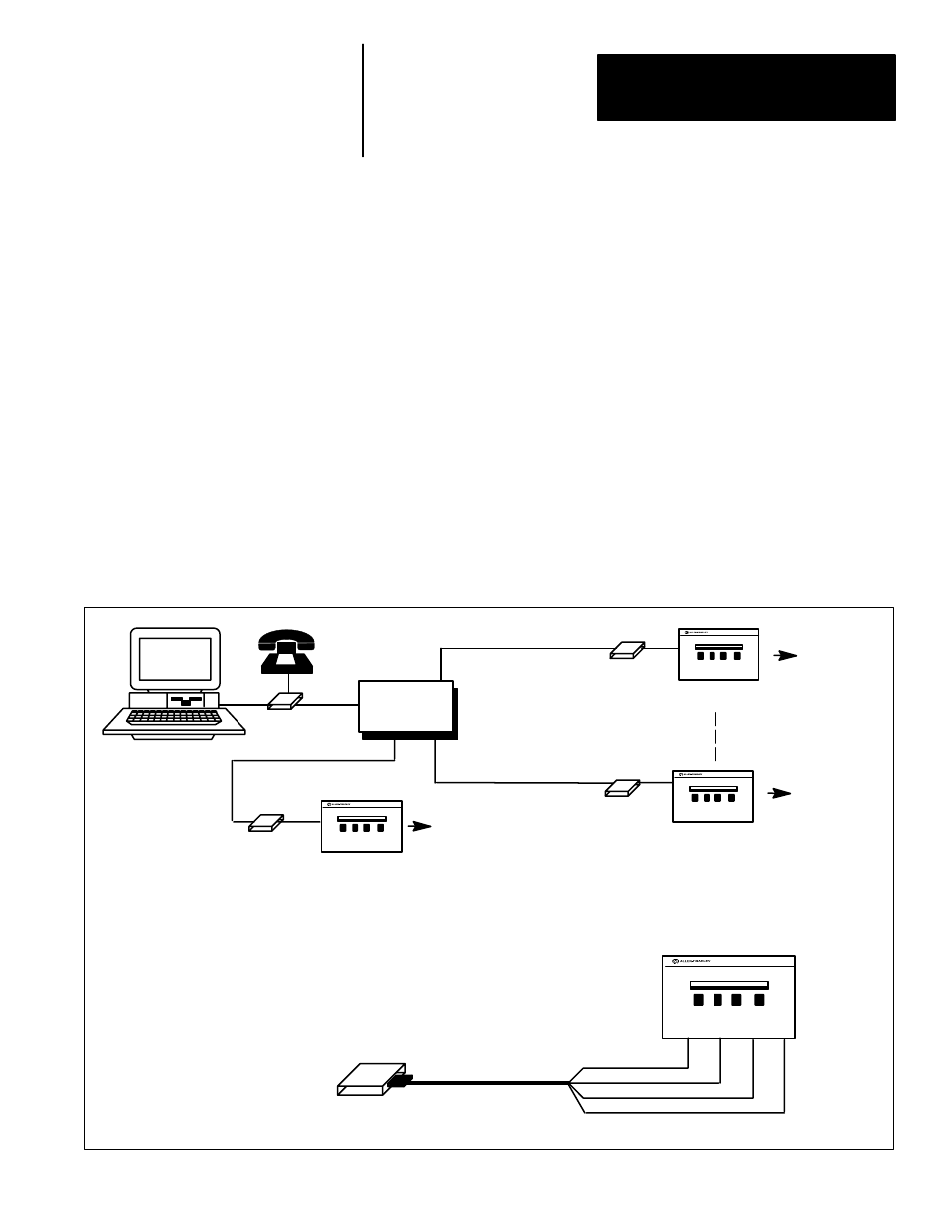
This section provides the information necessary to implement a telephone
modem link between the computer and sites with only single remote
Powermonitors.
Important: The multi–device remote site configuration outlined on page 3–8
should be used if more than one Powermonitor is to be installed at the remote
site in the future, or if a single device at a remote site is located more than 50
feet from the telephone modem.
To implement a telephone modem link, two telephone modems are required.
One modem must be located at the computer and one located at each remote
site requiring a Powermonitor. The single device port at the remote site must
be configured for an RS–232C communications port. The connection
diagram for the modem at the remote site is shown in Figure 3.3. Note that
this configuration (RS–232C) permits only one Powermonitor to be
connected to each modem.
Figure 3.3
Modem Connection to Sites with One Powermonitor
Telephone
Network
RS232C Cable
3
2
7
TXD
RXD
SG
Modem
Important: Note cable pin–out numbers
(DCE)
RS–232C
Modem
Modem
To Feeders,
Transducers, or
Pulse Initiations
Requiring
Monitoring
Powermonitor
Site 32
Site 2
Site 1
To Feeders,
Transducers, or
Pulse Initiations
Requiring
Monitors
To Feeders,
Transducers, or
Pulse Initiations
Requiring
Monitoring
Powermonitor
Powermonitor
Telephone
Line
Telephone
Line
Telephone
Line
Telephone
Line
Modem
RS–232C
RS–232C
Powermonitor
Modem
5
RTS
Connection To Single
Powermonitor Sites Via The
Telephone Network