Terminating resistors – Rockwell Automation 1500 DeviceNet MV Controllers Installation Instructions User Manual
Page 10
3-2
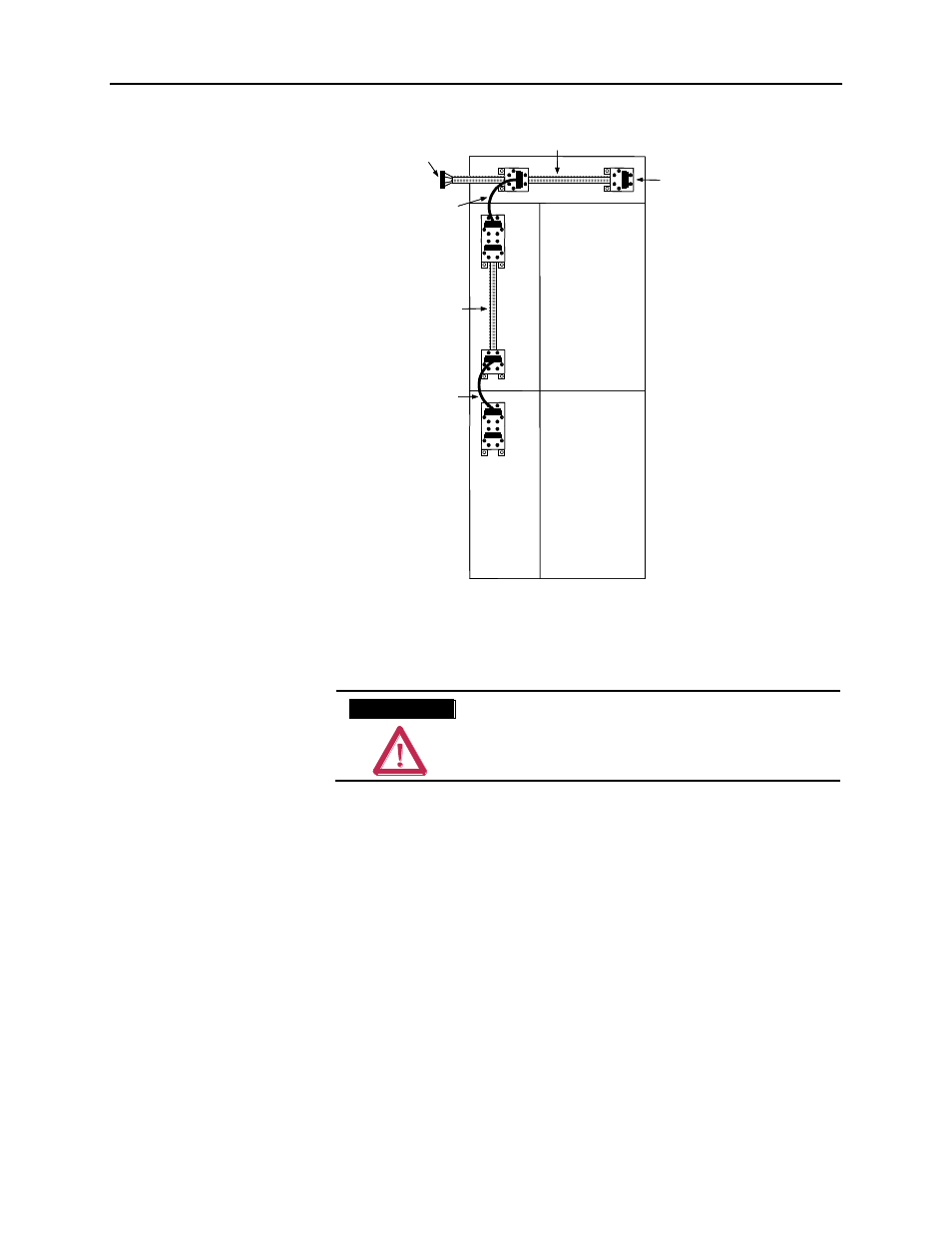
DeviceNet Cable System Layout for Medium Voltage Controller Structures
1500-IN057C-EN-P – June 2013
LV
LV
MV
MV
Female Linking Plug
Trunk Line
Drop Line
Drop Line Jumper
Male Linking Plug
Drop Line Jumper
LV
LV
MV
MV
Female Linking Plug
Trunk Line
Drop Line
Drop Line Jumper
Male Linking Plug
Drop Line Jumper
Figure 3.1 – Typical 2-High MV Section with DeviceNet Trunk and Drop Lines.
A T T E N T I O N
A T T E N T I O N
Before performing any service or maintenance
activities on MV MCC sections, disconnect all
power sources.
Terminating resistors are necessary at the ends of the trunk line to reduce
reflections of the communication signals on the network. The DeviceNet
network will operate correctly only when there are exactly two
terminating resistors, one at each end of the trunk line
. Terminating
resistors must be equal to 121 ohms 1%, 1/4W, metal film (terminating
resistor part number 1485A-C2).
MV controller line-ups ship with the terminating resistors installed at
opposite ends of the trunk line, located in the horizontal low voltage
wireway (on top of structure). A male plug connector with a terminating
resistor is connected at the right end of the trunk as shown in figure 3.2B.
A female plug connector with a terminating resistor is connected at the
left end of the trunk as shown in figure 3.2A. The resistors are inserted in
the second terminal from each end (connected to the white and blue
conductors) of both plugs (see diagram below).
Terminating Resistors