Alarm contact connections, Figure 5 - alarm contact, Power switch – Rockwell Automation 1608N MiniDySC User Manual, 2-6 Amp User Manual
Page 9: Operating indicators, Table 3 - list of conditions and indications
Rockwell Automation Publication 1608N-UM001B-EN-P - May 2014
9
Operation
Chapter 2
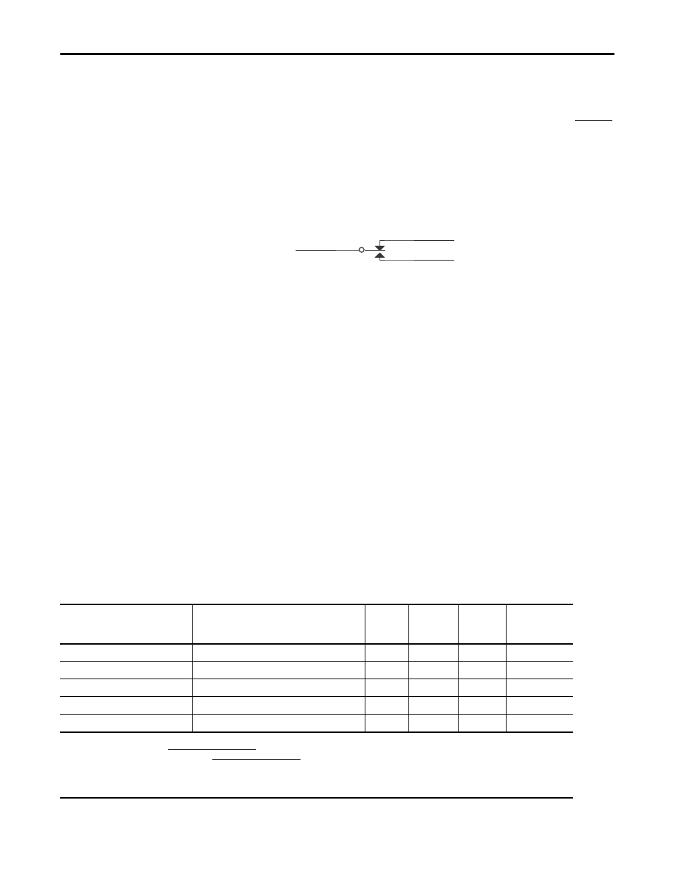
Alarm Contact Connections
•
The alarm contact will change states during any alarm condition. When the
alarm condition has cleared, the alarm relay will return to its normal state.
•
Terminal block pin numbers and Alarm contact ratings are shown in
Operation is as follows:
–
Normal Line Condition: pin 1 connects to pin 3.
–
Alarm Condition: pin 1 connects to pin 2.
–
Power Off Condition: pin 1 connects to pin 2.
Figure 5 - Alarm Contact
Power Switch
The service disconnect or the external branch circuit breaker may be used as a
master on/off switch.
Operating Indicators
•
When power is switched on, the Green light (Normal) on the front of the
MiniDySC will be lighted. The green light indicates that the output voltage
is within a normal range of -13% to +10% of nominal. This indicator will
also be on during sag correction events since the MiniDySC will be
maintaining the output voltage.
•
The Amber light (Alarm) flashes when the MiniDySC correction function
is inhibited. See Alarm Codes section below. The MiniDySC will resume its
corrective function and the flashing light will turn off when the alarm
condition has ceased. In a flashing amber light condition, the MiniDySC
will continue to pass the utility power to the load via the static switch.
•
The Red light will be on when the Static switch is inhibited due to an
overload condition. The MiniDySC will open the output. Power will need to
be cycled to reset the MiniDySC.
Table 3 - List of conditions and indications
2
1
NO
NC
COM
120 VAC .5 A
Alarm Relay Rating
3
30 VDC 1A
Condition
Description
Red
Light
Status
Green
Light
Status
Amber
Light
Status
Inverter
Operation
Status
Normal
88.5% < VLINE < 110% of Nominal
Off
On
Off
Off
Sag Event
VLINE < 88.5% while MiniDySC is correcting
Off
On
Off
Running
Runtime Exceeded
Cumulative runtime exceeded
Off
On
Flashing
Inhibited
Normal Mode, Static Switch Overload
Continuous Load current > 150%
On
Off
Off
Inhibited
Inverter Run Mode, Output Over current Load current > 150% for 3 cycles
Off
On
Flashing
Inhibited
Refer to Run Time specifications in
Technical Specifications on page 11
See Static Switch Maximum Current specifications in
Technical Specifications on page 11
If red LED is on, the output of the MiniDySC is inhibited and power needs to be cycled. If the problem reoccurs, the MiniDySC is overloaded.
On, provided output is within normal range
88.5
%< VLINE <110%.
Check Alarm Codes