Mounting instructions, Din rail mount, Figure 1 - din rail mounting – Rockwell Automation 1608N MiniDySC User Manual, 2-6 Amp User Manual
Page 6: Panel mount, Figure 2 - panel mounting, Do not remove the din mounting clips, Figure 1, Figure 2
6
Rockwell Automation Publication 1608N-UM001B-EN-P - May 2014
Chapter 1
Installation
Mounting Instructions
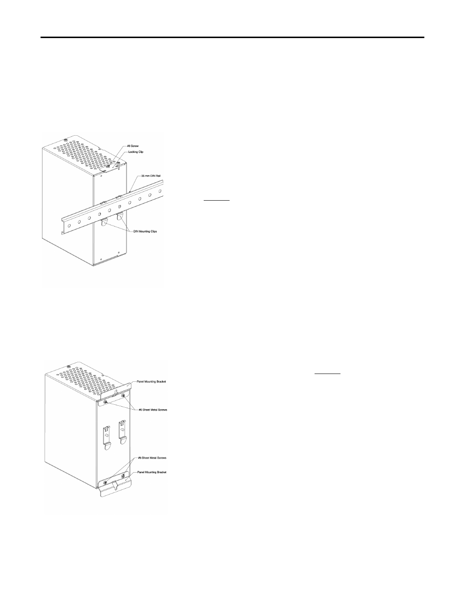
DIN Rail Mount
Figure 1 - DIN Rail Mounting
1.
Mount on a 35 x 7.5 mm DIN rail that conforms to the EN 50022
standard.
2.
The DIN mounting clips come pre-assembled to the back of the unit.
3.
Hook the top edge of the mounting clips over the top flange of the
DIN rail.
4.
Pivot the MiniDySC down until the unit latches to the DIN rail.
5.
To secure the MiniDySC to the DIN rail assemble the locking clip to the
top of the MiniDySC with one (1) of the #6 sheet metal screws supplied.
.
6.
An alternative method to using the locking clip to secure the MiniDySC to
the DIN rail is to use the lower panel-mounting bracket. Prior to mounting
the unit to the DIN rail install the lower panel-mounting bracket as
outlined under “Panel mounting instructions”. Once the unit is latched to
the DIN rail the unit can be secured to the mounting panel with a screw as
described under the panel mounting instructions.
Panel Mount
Figure 2 - Panel Mounting
1.
The MiniDySC may be panel mounted with the supplied hardware.
2.
Do not remove the DIN mounting clips.
3.
Attach the two (2) panel mounting brackets to the MiniDySC with four
(4) #6 sheet metal screws supplied. See
4.
The panel mounting brackets were designed to accept #8 - #10 hardware
with a maximum head diameter of 0.375" (9.5 mm).
5.
The center-to-center vertical mounting dimension for screw location is
8.65" (220 mm) on the 250 VA rated MiniDySC models and 9.65" (245
mm) on the 500 VA and 750 VA rated models.