Connection diagrams, Table 1 - fuse rating, Minidysc rating – Rockwell Automation 1608N MiniDySC User Manual, 2-6 Amp User Manual
Page 8: 250 va, 500 va, 750 va, Table 2 - fuse rating, Figure 3
8
Rockwell Automation Publication 1608N-UM001B-EN-P - May 2014
Chapter 2
Operation
Connection Diagrams
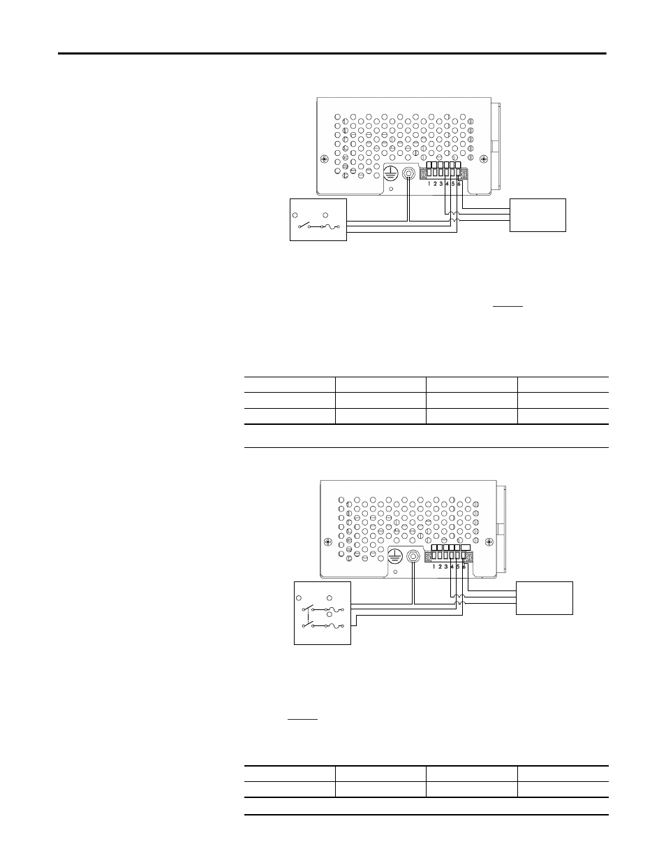
Figure 3 - 120, 220,230, 240 Volt, 1 Phase, Line-to-Neutral Connection Diagram
1.
User-supplied service disconnect (SW1). MiniDySC must be supplied through a
single pole switch in the "hot" line, with voltage and current ratings greater than or
equal to the MiniDySC ratings.
2.
User-supplied fuse (F1). AC input must be fused. See
fuse.
Note: Input neutral must be connected for all 120V, 220V and 230V applications. Failure to do so may result in
damage to the MiniDySC. Do not connect to a source with an AIC rating greater than 10,000 Arms.
Table 1 - Fuse Rating
Figure 4 - 208 & 240 Volt, 1 Phase, Line-to-Line Connection Diagram
1.
User-supplied service disconnect (SW1). MiniDySC must be supplied through a
double-pole switch located in both "hot" lines, with voltage and current ratings
greater than or equal to the MiniDySC ratings
2.
User-supplied fuses (F1, F2). Both hot lines of the AC input must be fused.
See
Note: Do not connect to a source with an AIC rating greater than 10,000 Arms
Table 2 - Fuse Rating
MiniDySC Rating
250 VA
500 VA
750 VA
120V
6A,120V
15A, 120V
15A, 120V
220...240V
3.2A, 250V
10A, 250V
10A, 250V
Recommended Fuses: Bussmann MDA-6 Bussmann FRN-R-15 Bussmann FRN-R-3-2/10
Bussmann FRN-R-10
MiniDySC Rating
250 VA
500 VA
750 VA
208..240V
3.2A, 250V
10A, 250V
10A, 250V
Recommended Fuses: Bussmann FRN-R-3-2/10 Bussmann FRN-R-10
C NC NO X1 L1 N
Input A.C.
SW1
F1
1
2
Ground
L1
Neutral
Neutral
Ground
X1
LOAD
LOAD
C NC NO X1 L1 L2/X2
Input A.C.
SW1
F1
1
2
Ground
L1
L2/X2
Ground
X1
LOAD
LOAD
F2
2
L2/X2