V-verb pro rev2496, 8 phaser, Effects – Behringer Rev2496 User Manual
Page 18
18
V-VERB PRO REV2496
There is a delay located ahead of each chorus voice. The
middle pre-delay time is set up using PREDLY (pre delay). The
DLYSPR (pre delay spread) determines the extent to which
delay times of individual chorus voices vary from one another.
When you select 0% as the value, all chorus voices are pre-
delayed with the same amount of PREDLY time.
The WAVE (LFO waveform) parameter describes the wave
form for the tone pitch modulation. Wave forms can be crossfaded
from triangle-shaped (0) to sinusoidal (50).
PHASE (LFO phase spread) and SPREAD (LFO frequency
spread) parameters are adjusted with the same control. They
control either the phase length or the LFO frequency of the
individual chorus voices. In PHASE mode (the potentiometer points
between the left-most position and the middle), all LFOs have the
same frequency, and the phase difference of the individual LFO
generators can be adjusted between 0° (no phase difference)
to 180° (maximum phase difference). When in SPREAD mode
(the potentiometer lies between the middle and the right-most
position), you can determine the extent to which the LFO
frequency (adjusted with SPEED) between individual chorus
voices will vary. In the middle position (0%), all LFOs run
synchronously.
The chorus effect features the so-called auto-panning function.
This way, you can shift the individual chorus voices around
from left to right in the stereo image. With the PAN (panning
mode) parameter, you determine the auto-panning operating
mode. You can select between OFF, SYNC and RAND. When
set to SYNC, all chorus voices are shifted by the same frequency
in the stereo image. RAND (random) shifts each chorus voice
with a somewhat different velocity. OFF deactivates this function.
The PANSPD (panning speed) parameter controls the median
panning speed.
The flanger effect is produced when the modulated signal is
fed back to the input signal through a feedback loop. The FEEDB
(feedback amount) parameter controls feedback intensity.
Negative values produce reverse-phase feedback.
Two shelving filters are integrated into the feedback loop.
These shelving filters are used to filter the signal that is fed back
into the input signal. LO FREQ (low frequency) and LO GAIN
(low gain) process the bass frequencies, while HI FREQ (high
frequency) and HI GAIN (high gain) set up the frequency and
the attenuation of treble frequencies. The graphic representation
of this page shows the resulting frequency distribution.
CROSSF (cross feedback amount) is a unique function that
lets you feed back both channels in a crisscross fashion, i.e.
from the right to the left channel and vice versa. A value of 100%
results in the effect signal of the left channel being exclusively
fed into the right channel and vice versa. This parameter is
dependent on the previously set feedback intensity.
With LFOMOD (LFO feedback modulation amount) parameter,
you can modulate the volume of the feedback signal. When you
set this parameter to the maximum, you get volume variation
between zero and the value set with FEEDB.
The median LFO speed can also be influenced through the
input signal level (so-called auto modulation). Using the LFOMOD
(envelope to LFO speed modulation) parameter on the envelope
page, a maximum increase of the LFO speed is determined by
the signal volume. The ATTACK (attack time) parameter controls
how quickly the LFO speed increases when the signal volume
goes up. HOLD (hold time) determines how long the LFO speed
is kept constant when the signal volume begins to decrease.
RELEAS (release time) determines how quickly the LFO
frequency decreases after the HOLD time ends.
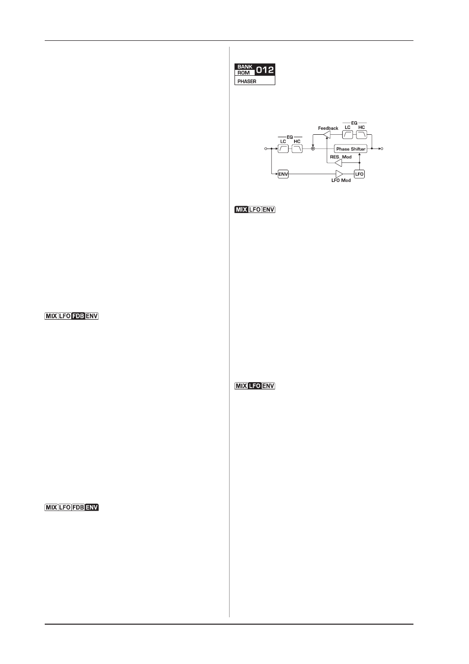
4.8 Phaser
This algorithm can create different kinds of typical phaser
effects. The number of phase shifting stages used can be set to
between 4 and 12.
Fig. 4.8: Phaser effect design
The MIX (effect mix) controls the mix ratio between the dry
signal (0%) and the effect signal (100%). The phaser effect is
intensified through the mix between the input signal and the out-
of-pitch signal. The effect comes through most powerfully when
the MIX value is set between 50 and 70 percent.
A combination of the high pass filter and the low pass filter
reduces the bandwidth of the input signal. These filters are
controlled with LO CUT (low cut frequency) and HI CUT (high
cut frequency).
Using STAGES, you can set up the number of phase shifting
stages used. You can select between 4 and 12 stages. RESON
(resonance) controls how much feedback the effect signal
produces at the input. Two filters are also integrated in the
feedback loop. RES HC (resonance high cut frequency)
determines the frequency of a low pass filter, while RES LC
(resonance low cut filter) sets the frequency of a high pass
filter.
With GAIN (output gain), you can correct the output volume of
the effect block (engine).
SPEED (modulation speed) determines modulation speed and
can also be entered using the TAP key.
The WAVE (LFO waveform) parameter can be used to lengthen
the upper or the lower alternation of the LFO triangle oscillation.
Negative values lengthen the lower alternation; positive values
lengthen the upper alternation. The influence of these parameters
on the wave form is clarified on the GRAPH page.
PHASE (LFO phase spread) and SPREAD (LFO frequency
spread) parameters are adjusted by the same control. They
control the phasing or the frequency of both LFOs for the left
and right channels. In PHASE mode (the potentiometer points to
the left of its middle position), the LFO frequency remains
unchanged, while the phase difference can be set to values
between 0° and 180°. When the potentiometer points to the right
of its middle position (SPREAD mode), the LFO frequency
deviation in both channels is controlled. At 0%, both LFOs operate
at the same frequency (set with SPEED ), while 100% creates a
maximum deviation of both LFO frequencies.
RANGE (sweep range) defines the maximum phase shift. With
DEPTH (LFO modulation depth), you can set the phase shift
modulation depth through the LFO. A value of 100% means that
the LFO modulates the phase shift between the value set using
RANGE and the minimum value.
With COLOR, you can determine the characteristic of the
phase-shifted sound. A low setting creates the sound of a
standard phaser, while higher values lead to more intensive
sound effects.
4. EFFECTS