V-verb pro rev2496, Operation – Behringer Rev2496 User Manual
Page 13
13
V-VERB PRO REV2496
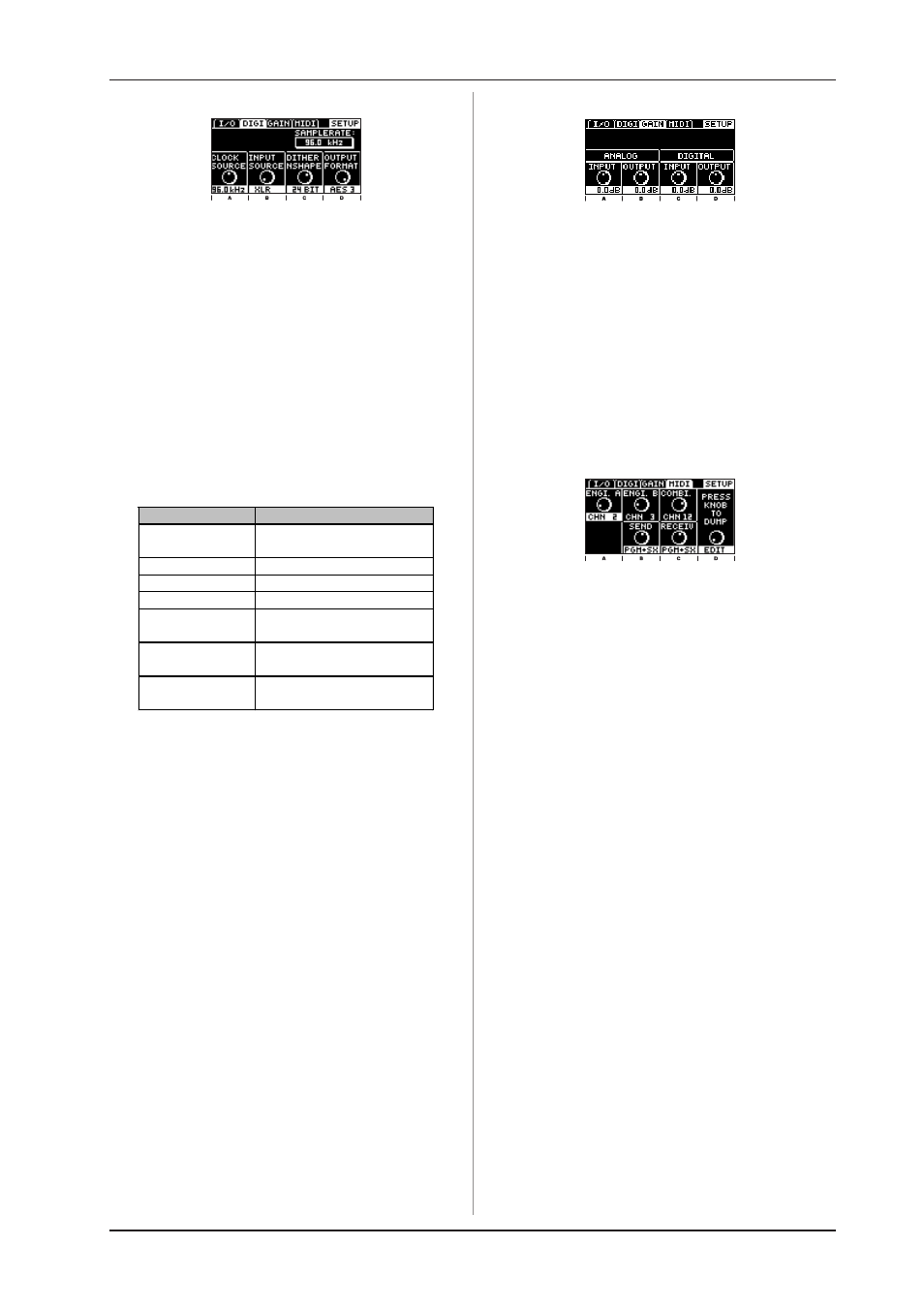
3.8.2 DIGI page
Fig. 3.10: SETUP page 2
Clock Source: Here you can select the clock speed of the
REV2496. You can select between the following internal clock
speeds: 44.1, 48 or 96 kHz. If you wish to externally synchronize
your REV2496 (slave operation), you can select if the clock
speed will be via the external BNC wordclock input (WDCLK) or
via the digital input (DIG. IN). If you wish to use your REV2496 as
a slave and at the same time wish to use the analog inputs, a
synchronization via the wordclock input or via one of the two
digital inputs is necessary.
Input Source: With the EDIT B control, you can decide which
of the two digital inputs will be used: the optical input (OPT.) or
the XLR input (XLR).
Dither and Noise Shaper: The EDIT C control has a dual
function. Here, you can select if you want to accomplish dithering
for the digital output signals, or if you also want to use additional
noise-shaping. The following settings can be made:
Dis play
Func tion
OFF
Dithering and Noise Shaper
deactiv ated
24 BIT
Only dithering at 24 bit
20 BIT
Only dithering at 20 bit
16 BIT
Only dithering at 16 bit
24 BIT (+NSHA PE) Dithering w ith ac tivated
Nois e Shaper at 24 bit
20 BIT (+NSHA PE) Dithering w ith ac tivated
Nois e Shaper at 20 bit
16 BIT (+NSHA PE) Dithering w ith ac tivated
Nois e Shaper at 16 bit
Tab. 3.4: Setting possibilities for
dithering and noise shaping
+
Dithering refers to a low-level signal that is added
to the audio signal in order to reduce the so-called
quantization. It should be adjusted to the word rate
(bit rate) that the associated equipment can support.
The Noise-Shaping function displaces the noises
created through dithering into a less perceptible
frequency range.
Output Format: The EDIT D control adjusts the format of the
digital data flow at the output. The professional AES/EBU (AES3)
format and the consumer S/PDIF format are available. The selected
format applies to both digital outputs, i.e. if you use an appropriate
cable, you can forward a signal from the XLR output in the
S/PDIF format to another piece of equipment with a
S/PDIF connection.
3.8.3 GAIN page
Fig. 3.11: SETUP page 3
Here, you can adjust the signal level of analog and digital
inputs and outputs. A signal level adjustment of +/- 6 dB is possible.
The REV2496 features two automatic, non-disengageable
Peak Limiters in the output section of both engines. If signal
peaks occur, these peak limiters effectively eliminate them. If the
peak limiters engage, the corresponding LIMITER LED illumi-
nates. In this case, please reduce the input/output level until the
LED is no longer illuminated or only lights up occasionally.
The level indicator of your REV2496 indicates the input that
was selected as master input on the I/O page of the setup menu.
During level setting of the digital input, if you want to see a signal
on the LED ring, you have to select this input as master input.
3.8.4 MIDI page
Fig. 3.12: SETUP page 4
On this page, you can perform MIDI adjustments. For ENGINE
A, B and for COMBI., different MIDI channels can be selected.
This way, you can separately switch presets for both processors
and assign different MIDI controllers.
The parameters SEND and RECEIVE let you activate individual
MIDI functions on both the send and the receive ends. These
are: Program Change, Controller and SysEx (system-exclusive
data).
If you wish to carry out a MIDI dump, use EDIT D to determine
beforehand if all user presets (ALL) or only the current setting
of the selected combination and the settings of both engines
(EDIT) are transmitted as SysEx data.
All MIDI functions are explained in detail in chapter 6.
3. OPERATION