V-verb pro rev2496, 6 xover delay, 7 chorus/flanger – Behringer Rev2496 User Manual
Page 17: Effects
17
V-VERB PRO REV2496
GAIN 1 determines the output level, and BAL 1 (balance)
determines the position of the delayed signal in the stereo image.
The second delay is designed identically to delay 1. Here, too,
there is a pre-delay located ahead of the feedback loop. DELAY
2 (delay time) determines the delay time of main delay. The
parameters FEEDB, GAIN 2 and BAL 2 have the same function
as in Delay 1.
+
The time values of delay 1 and delay 2 can
alternatively be adjusted by tapping the TAP key.
The key LED blinks rhythmically in the tempo of the
delay time you adjusted.
An equalizer (EQ) is integrated in the feedback paths of both
delays. This equalizer lets you filter the signal in the feedback
path. All filter settings of this section have an effect of both
delay feedbacks.
The equalizer consists of two shelving filters; LO FREQ (low
frequency)/LO GAIN (low gain) process the bass filter, while HI
FREQ/HI GAIN adjust the frequency and the level of the treble
filter.
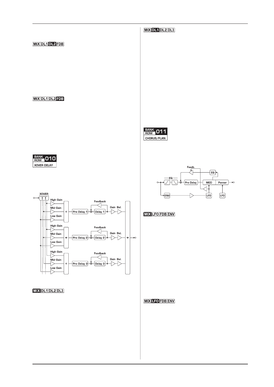
4.6 XOver Delay
The input signal is divided into bass, mids and highs. The
elements of the individual frequency bands can be assigned to
three separate stereo delays with separate levels. This way,
interesting reflexion patterns can be produced.
Fig. 4.6: Effect design of the Xover delay effect
The mix ratio between the effect and the dry signal is controlled
with the FX LVL (effect level) and DRY parameters. DRY is not
available in the EXTERNAL mix mode (pre-adjustable in setup) as
well.
The crossover parameters can also be adjusted. HI TYPE
(high filter type) determines the slope of the crossover between
the high and mid frequency bands. You can select between 6,
12 and 18 dB per octave. The split frequency of this filter is
adjusted using HI FREQ (high split frequency).
LO TYPE (low filter type) determines the slope of the lower
filter (6, 12 and 18 dB per octave). The crossover frequency for
this filter is adjusted using LO FREQ (low split frequency).
Each one of the three delay modules has its own EDIT page.
Because the functions are basically the same, we will only
describe them once.
Next, you can determine how much of the signal from each
individual frequency band will be added to the delay section. The
parameters LO GAIN (low input gain), MD GAIN (mid input gain)
and HI GAIN (high input gain) are used for this purpose.
The PREDLY (pre delay) parameter determines the delay time
of a special delay that is not part of the feedback loop. With
DELAY (1, 2, 3) you can adjust the delay time of the delay
sections and can also be entered using the TAP key. With FEEDB
(feedback amount) you can vary the amount of feedback.
Negative values produce reverse-phase feedback.
The output signals of the delay units can be mixed with
GAIN (1, 2, 3) and positioned within the stereo image using BAL
1, 2, 3 (balance).
4.7 Chorus/flanger
The chorus/flanger effect can operate in 4 different modes:
stereo chorus, 4, 6 and 8-voice chorus. Additionally, the signal
whose pitch has been modulated can be fed back to the input,
whereby flanger effects can be created.
Fig. 4.7: Effect design for chorus/flanger
The MIX (effect mix) parameter controls the effect-mix ratio.
A value of 0% reproduces only the input signal; a value of 100%
reproduces only the effect signal. Hint: mixing the input signal
and the out-of-tune signal makes the chorus effect even more
intensive. The effect is at its strongest with values between 40
and 60 percent.
The input signals bass and treble frequencies can be filtered
using the 2-band equalizer (EQ). HI FREQ/HI GAIN and LO FREQ/
LO GAIN can be used.
Using MODE, you can select the operating mode for chorus.
STEREO (stereo chorus), QUAD (4-voice chorus), HEXA
(6-voice chorus) and OCTA (8-voice chorus) can be selected.
With the GAIN (output gain) parameter you can correct the output
volume of the effect block (engine). The ST SPR (stereo spread)
parameter defines the stereo width of the effect signal between
mono signal (0%) and maximum stereo width (100%).
A very essential element of any chorus/flanger effect is its
LFO (low frequency oscillator), which is used for creating
modulations. The SPEED (modulation speed) parameter controls
the modulations velocity. This value can alternatively be entered
using the TAP key.
With chorus/flanger, the modulations delay time influences
the intensity of the effect. This value is set up using MODDLY
(modulation delay). Short times create a more subtle effect, while
longer delays produce stronger pitch variations.
4. EFFECTS