Accessing terminations, Figure 5 - knockout hole locations, L-n versus l-l configuration – Rockwell Automation 1608N MiniDySC User Manual, 12-50 Amp User Manual
Page 10: Line to neutral, Figure 6 - line to neutral configuration
10
Rockwell Automation Publication 1608N-UM002B-EN-P - May 2014
Chapter 1
Installation
Accessing Terminations
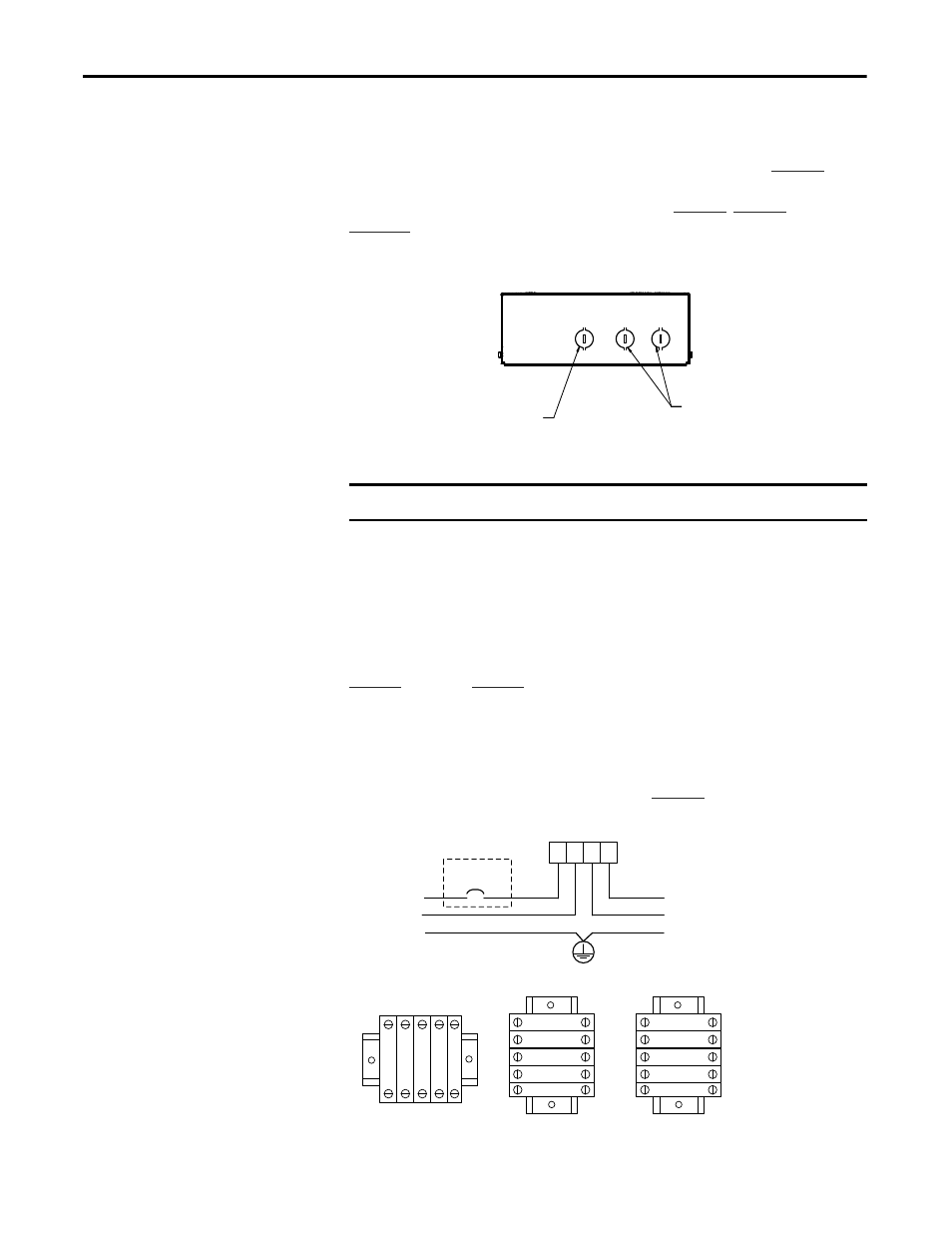
Three knockout holes are provided for conduit entry, as shown in
. Take
care to avoid dropping any metal filings inside the enclosure. Metallic
contamination will void the product warranty. See
, and
for input/output terminal locations.
Figure 5 - Knockout Hole Locations
L-N Versus L-L Configuration
MiniDySC terminals are labeled in accordance with the AC input source type.
Bulletin 1608N part numbers containing V2 are configured for single-phase
line-to-neutral (phase-to-neutral) input, with input terminals labeled L1 and N. Part
numbers containing V1 are configured for line-to-line (phase-to-phase) input, with
input terminals labeled L1 and L2. Select the correct connection diagram between
(L-N) and
(L-L).
Line to Neutral
MiniDySC L-N models must be connected as in
Figure 6 - Line to Neutral Configuration
IMPORTANT
Metallic Particles inside the enclosure will void the warranty
COMMUNICATIONS
.89 [22.6mm] DIAMETER EKO
2X INPUT AND OUTPUT
AC CONNECTIONS.
.89 [22.6mm] DIAMETER EKO
GR
X1
N
N
L1
GR
L1
N
N
X1
GR
X1
N
N
L1
INPUT SOURCE
User Supplied
Circuit Breaker
L1
N
GND
GROUND
STUD
OUTPUT TO LOADS
X1
N
GND
X1
N
N
L1
L-N
25A ER
50A SR/ER
12A-25A SR
Terminal Block Configurations