Rockwell Automation 161 SERIES B FRN 2.001 User Manual
Page 27
23
Parameters & Programming
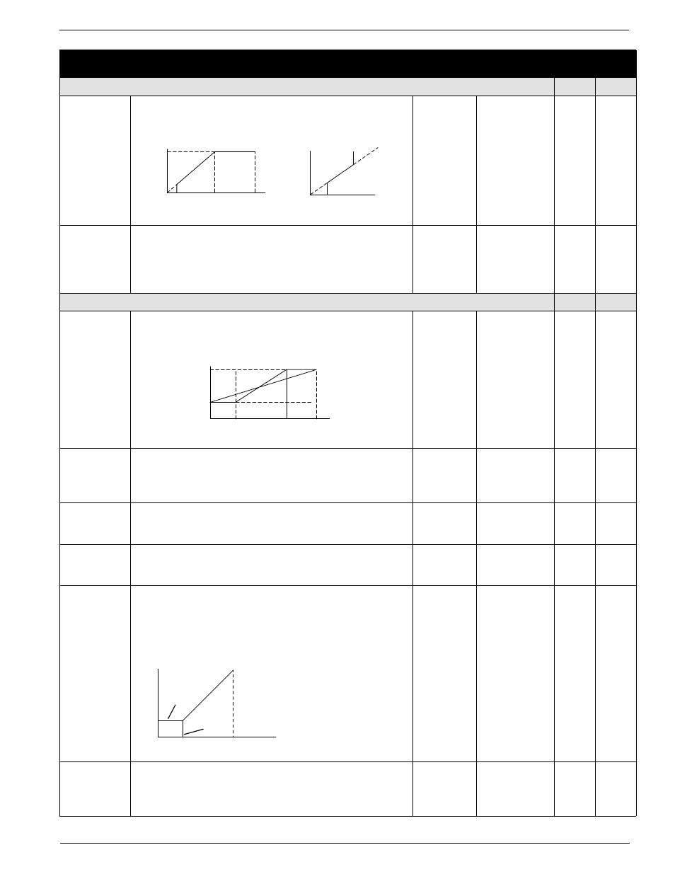
A03
[Base Frequency]
Set value to rated nameplate frequency of motor
50/360
1 Hz
60
50
A04
[Maximum Frequency]
Highest frequency the drive will output.
Note: If a maximum frequency less than
PA03 – [Base Frequency] is
needed, use
PA61 – [Upper Frequency Limit].
Refer to diagram in
PA03 – [Base Frequency].
50/360
1Hz
60
50
Analog input reference adjustment
U
1
K
1
A11
[Analog Frequency Minimum]
Sets the frequency that corresponds to a 0V or 4mA
analog signal.
0.0/360.0
0.1 Hz
0.0
0.0
A12
[Analog Frequency Maximum]
Sets the frequency that corresponds to a 10V or 20mA
analog signal. A value of 0.0 will disable this function.
Refer to diagram in
PA11 – [Analog Frequency Minimum].
0.0/360.0
0.1 Hz
0.0
0.0
A13
[Analog Input Minimum]
Sets the starting point (offset) for the analog input range.
Refer to diagram in
PA11 - [Analog Frequency Minimum]
0/99
1%
0
0
A14
[Analog Input Maximum]
The ending point (offset) for the analog input range.
Refer
to diagram in
PA11 - [Analog Frequency Minimum].
0/100
1%
100
100
A15
[Analog Start Select]
Sets the output frequency when frequency reference is
below value set in PA13 – [Analog Input Minimum].
Settings:
00 = PA11 - [Analog Frequency Minimum]
01 = 0 Hz
00/01
Numeric Value
01
01
A16
[Analog Filter Select]
Sets the level of the Analog input smoothing filter where:
1 = low. (Bandwidth = 200 Hz)
8 = high. (Bandwidth = 25 Hz)
1/8
Numeric Value
8
8
Parameter
Number
Parameter Name / Description
Min./Max
Range
Units
Factory
Defaults
Basic Functions
U
1
K
1
Voltage
100%
0
Start
Frequency
b82
Base
Frequency
A03
Maximum
Frequency
Frequency
Frequency
Frequency Limit
A61
Minimum
Frequency
A62
Hz
Command
Upper
A04
A12
A11
0V
10V
A13
A14
4mA
20mA
% Input
Scale
Frequency
A15=00
A15=01
A12
A11
0V
10V
A13
A14
4mA
20mA
% Input
Scale