Setting the devicenet node address – Rockwell Automation 855T DeviceNet Stack Light User Manual User Manual
Page 28
3-3 Installation and Mounting
Publication 855T-UM001C-EN-P May 2005
The data rate determines the maximum length of the DeviceNet Cable.
To set the DeviceNet data rate:
1. Refer to the table above to select the correct data rate.
2. If automatic baud rate selection is desired, set switch 3 (S3) in position 3. This
disables the switch and allows the device to sync to an operational network (if
Autobaud is disabled through parameter setup, this position is not valid).
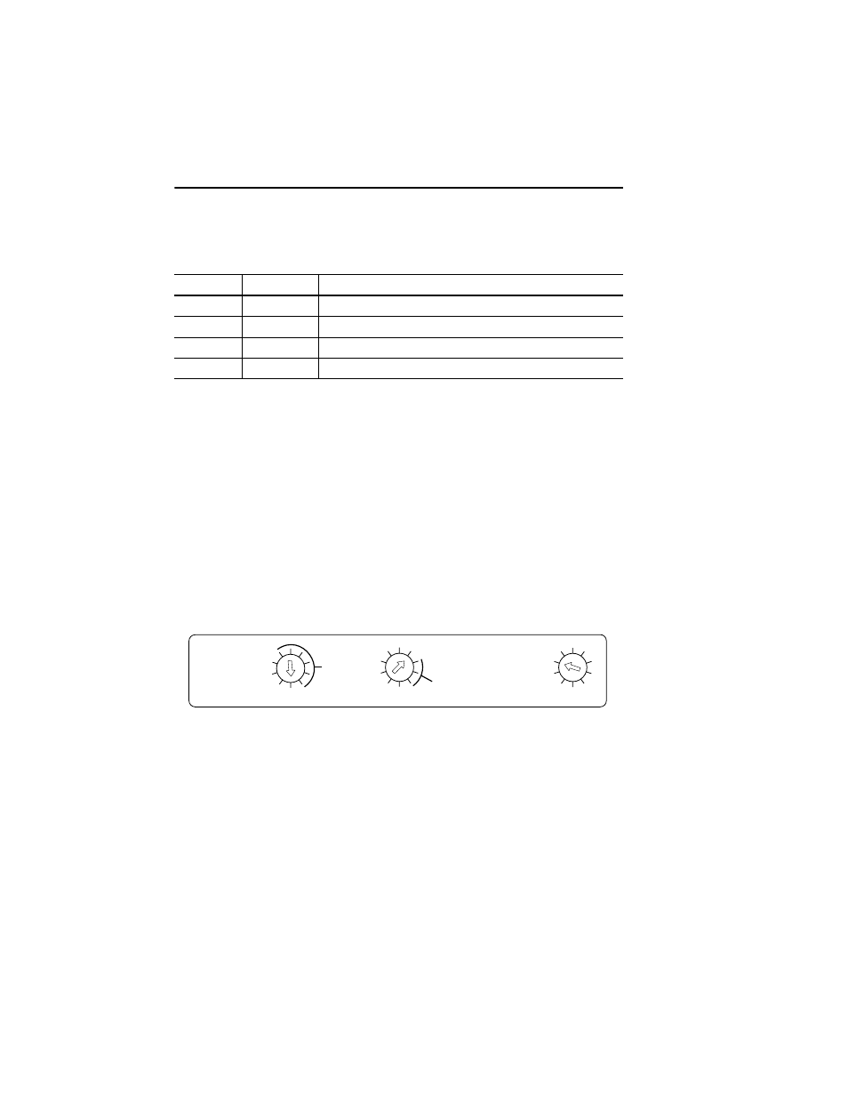
Setting the DeviceNet Node Address
Rotary switches 1 (S1) and 2 (S2) set the node address (0…63) of the stack light on the
DeviceNet Network. The factory default is 63.
Figure 3.3
To set the DeviceNet node address:
1. Set Most Significant Digit (MSD) Switch, switch 2 (S2), to tens position. For example,
if the desired node address is 27, set switch 2 (S2) to 2.
2. Set Least Significant Digit (LSD) Switch, switch 1 (S1), to ones position. For example,
if the desired node address is 27, set switch 1 (S1) to 7.
3. If software programmability is desired, set the node address to 64 or greater. This
disables both switches and allows programming through the network. Software will
default to 63.
Table 3.B
Position
Data Rate
Cable Length (Max.)
0
125 KB
500 m (1600 ft)
1
250 KB
200 m (600 ft)
2
500 KB
100 m (300 ft)
3
Autobaud
See above, based on data rate of connected network
DATA
RATE
PGM
500K
250K
NOT
USED
MSD
NODE ADDRESS
(00 – 63, PGM)
4
6
2
0
8
125K
PGM
0
LSD
2
4
6