General safety information, Mount the msr57p relay, Spacing requirements – Rockwell Automation 440R-S845AER-NNL MSR57P GuardMaster Speed Monitoring Safety Relay User Manual
Page 3
GuardMaster MSR57P Speed Monitoring Safety Relay 3
Publication 440R-IN016B-EN-P - November 2008
General Safety Information
Retain these instructions for future reference. Rockwell Automation cannot accept
responsibility or liability for a failure of this device if the product is used outside the
recommended specifications in this document.
Spacing Requirements
Adequate air space must be provided around the system (module cluster). Minimum
recommended clearances:
•
15 mm (0.6 in.) above
•
15 mm (0.6 in.) below
•
2…3 mm (0.08…0.12 in.) between modules at ambient temperatures higher
than 40 °C (104 °F).
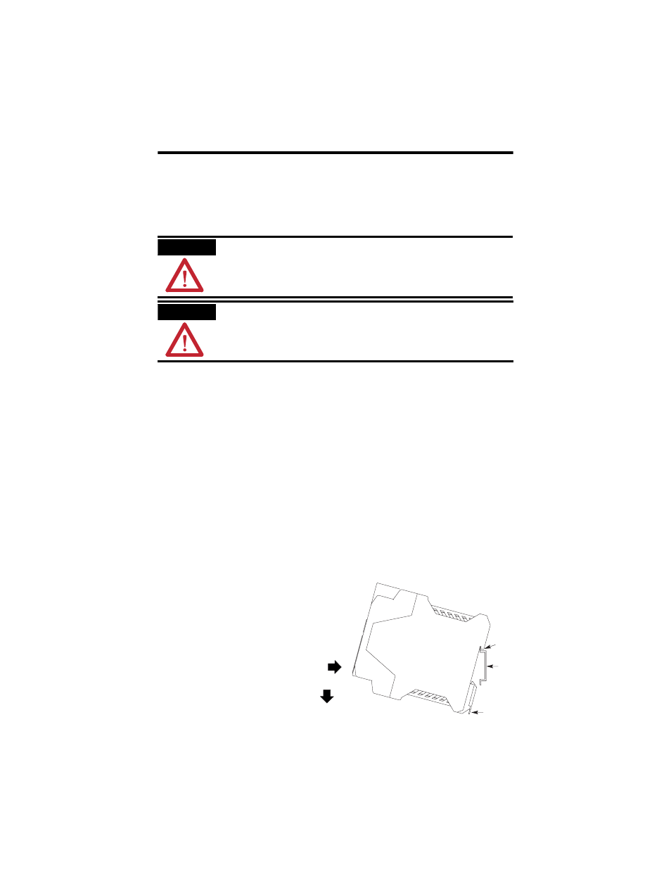
Mount the MSR57P Relay
Follow these steps to mount the MSR57P relay to an EN50022 -35 x 7.5 DIN rail.
1. Hook the top slot over the DIN
rail.
2. Snap the bottom of the device
into position while pressing the
device down against the top of
the rail.
3. Attach end plates on each end
of the DIN rail.
To remove the device from the DIN rail,
use a flathead screwdriver to pull down
the latch and lift the device from the rail.
ATTENTION
This device is intended to be part of the safety-related control system of a machine. Before
installation, a risk assessment should be performed to determine whether the specifications
of this device are suitable for all foreseeable operational and environmental characteristics
for the machine to which it is to be fitted. At regular intervals during the life of the machine,
check whether the characteristics foreseen remain valid.
ATTENTION
Safety Programmable Electronic Systems (PES)
Personnel responsible for the installation and application of safety-related programmable
electronic systems (PES) shall be aware of the safety requirements in the application of the
system and shall be trained in using the system.
Slot
DIN
Rail
Latch