Figure 8.4 reading and writing drive parameters – Rockwell Automation 160 RSI SERIAL COMM MODULE User Manual
Page 38
8–6
Using the RS1 Module with a Programmable Controller
Figure 8.4
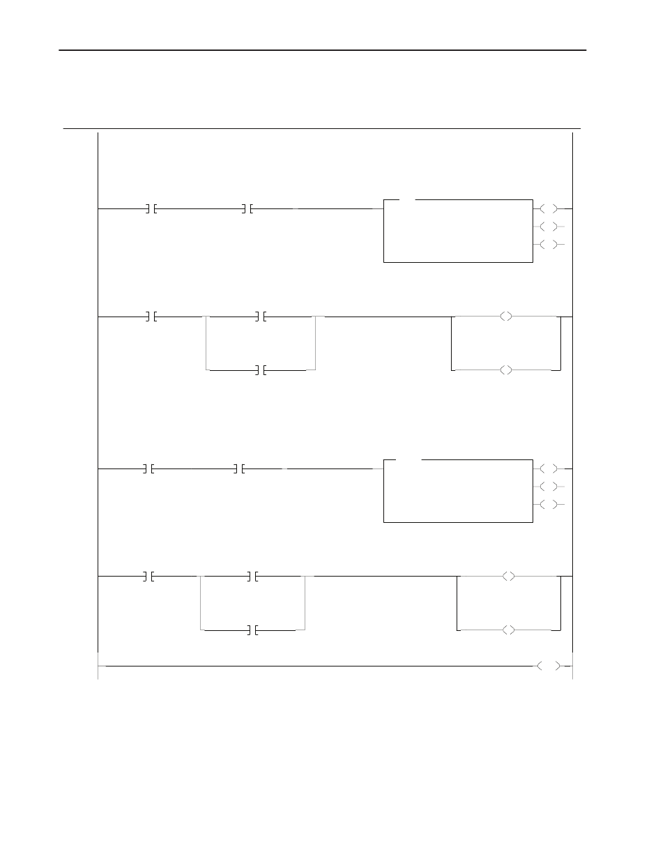
Reading and Writing Drive Parameters
LAD 5 - PARAMETER --- Total Rungs in File = 5
Parameter Write - when it's time to perform a parameter write B3:0.4 and B3:1.4 will be set. Data from N7:51 will written out Channel 0
to the 160 - RS1 module at location N10:30 (parameter 30). To write to a different parameter, change word 5 of the control word (N7:41)
to the new parameter number.
0000
B3:0
4
Enable Bit -
Parameter write
control
B3:1
4
Parameter Write
Request Bit
EN
DN
ER
MSG
Read/Write Message
Read/Write
Write
Target Device
500CPU
Control Block
N7:36
Control Block Length
7
Setup Screen
Parameter Write-
Data N7:51 is wrote
to RS1 module N10:30
0001
B3:0
4
Enable Bit -
Parameter write
control
N7:36
13
Done Bit -
Parameter Write
N7:36
12
Error Bit -
Parameter Write
U
B3:0
4
Enable Bit -
Parameter write
control
U
B3:1
4
Parameter Write
Request Bit
Parameter Read - when it's time to perform a parameter read B3:0.5 and B3:1.5 will be set. Data from the RS1 module
N10:30 (parameter 30) will be read through Channel 0 back to the controller and placed in N7:52 . To read a different parameter,
change word 5 of the control word (N7:49) to the new parameter number.
0002
B3:0
5
Enable Bit -
Parameter Read
control
B3:1
5
Parameter Read
Request Bit
EN
DN
ER
MSG
Read/Write Message
Read/Write
Read
Target Device
500CPU
Control Block
N7:44
Control Block Length
7
Setup Screen
0003
B3:0
5
Enable Bit -
Parameter Read
control
N7:44
13
Done Bit -
Parameter Read
N7:44
12
Error Bit -
Parameter Read
U
B3:0
5
Enable Bit -
Parameter Read
control
U
B3:1
5
Parameter Read
Request Bit
0004
END