Chapter, Required tools, Example network – Rockwell Automation 160 RSI SERIAL COMM MODULE User Manual
Page 33
Chapter
8
Using the RS1 Module with a
Programmable Controller
This chapter provides an overview of the steps needed to use the RS1
Module with a MicroLogix 1000 (or other Allen-Bradley
programmable controllers). The programmable controller can send
control messages to the RS1 Module and receive status messages
back. The device also allows a ladder logic program to configure and
read parameters from the 160 Drive.
This chapter contains the following information:
•
How to setup the RS1 Module with a programmable controller.
•
A sample ladder logic program to control the 160 Drive.
•
A description of reading parameters using the Message (MSG)
Command.
•
A sample ladder logic program to read parameters.
The MicroLogix 1000 Programmable Controller was used with
RSLogix 500™ software for the examples shown in this chapter – the
concepts demonstrated apply to other programmable controllers as
well, including the SLC 500 and PLC-5.
Before continuing, the user should have read and understood:
•
MicroLogic 1000 Programmable Controller User Manual,
Publication 1761-6.3 (or appropriate controller User Manual).
•
SLC 500 and MicroLogix 1000 Instruction Set Reference Manual,
publication 1747-6.15.
Required Tools
The following tools will be needed to complete this chapter:
•
160 Drive equipped with an RS1 Communication Module.
•
MicroLogix 1000 Programmable Controller.
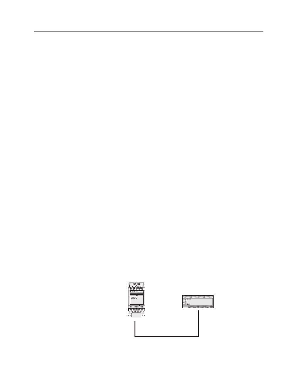
Example Network
160 Drive with RS1
MicroLogix 1000
FAULT
READY
RS232
Serial Comm
COMM