Rockwell Automation 160 RSI SERIAL COMM MODULE User Manual
Page 27
Parameter Descriptions
6–3
130
30
Read
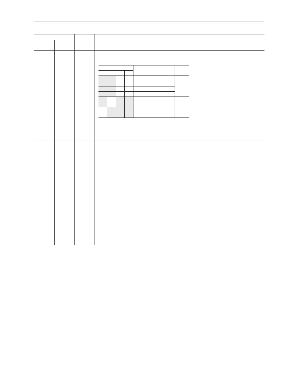
[DIP Switches]
Displays the current DIP switch settings.
0 to 0xF
0 to 15
0000
131
31
Read
[Actual Speed]
Returns speed feedback from the drive. This is the actual drive speed
scaled from 0 to 32767, where 0 = 0 Hz and 32767 = P33 - [Maximum
Frequency].
0 to 32767
0
132
32
Read
[Logic Status]
Returns logic status (N41:0). Refer to page 5–3 for data format.
0 to 65535
0
133
33
Read/Write [Logic Mask]
This parameter determines the source of the drive control logic.
A value of “1” corresponds to terminal block control, and any drive input
mode (P46 - [Input Mode]) value except “2” or “6.”
A value of “2” corresponds to RS1 Module logic control. The input mode
value is “2” or “6.”
If the Logic Mask value is changed from “1” to “2,” the terminal block logic
control is masked out by the RS1 Module. The module does this by
changing the Input Mode to the last previously active network mode, “2” or
“6” (if a network mode has not been active since drive power was applied,
it is set to “2”).
If the Logic Mask value is changed from “2” to “1,” the RS1 logic control is
masked out by the RS1 Module. The module does this by changing the
Input Mode to the last previously active non-network mode (if a non-
network mode has not been active since drive power was applied, it is set
to “0”).
IMPORTANT: Power must be cycled or P56-[Reset Functions] must be
set to “2” for this change to take affect.
1 to 2
1
Parameter Number
Access
[Parameter Name] and Description
Min./Max.
Values
Default
Drive
(N10:, N30:)
RS1
(N13:, N33:)
Bit
Description
Switch
3
2
1
0
0
0
9600 (Default)
SW1,
SW2
0
1
2400
1
0
1200
1
1
EPROM Mode
0
DF1 Point-to-Point (Default)
SW3
1
DF1 Multi-Drop
0
BCC (Default)
SW4
1
CRC