Install components – Rockwell Automation 20B PowerFlex 700 Drive Components Replacement - Frame 8 User Manual
Page 46
46
Rockwell Automation Publication 20B-IN024C-EN-P - June 2012
Chapter 3
Component Replacement Procedures
Install Components
1. Use a 3 mm angle hex wrench to replace the setscrews for each new
capacitor. Torque to 0.7 N•m (6 lb•in).
2. Place capacitors into correct position in drive (vent plug at top or 12
o’clock).
3. Place bus capacitor busbar onto capacitors.
4. Install the 18 washers and nuts onto setscrews, but do not tighten yet.
5. Place the transitional busbar in position. Make sure that all setscrews,
washers, and nuts fit. Adjust as needed.
6. Remove the transitional busbar, and tighten all washers and nuts for the
bus capacitor busbar. Torque to 5.6 N•m (50 lb•in).
7. Install the transitional busbar assembly as detailed on
8. Replace all safety shields and enclosure covers before applying power to the
drive.
ATTENTION:
Install each capacitor so its vent plug is at the
top
or 12 o’clock. Component and system damage may result if
you position any bus capacitor incorrectly.
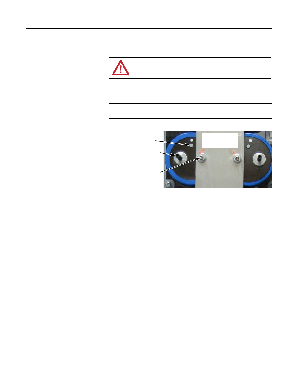
IMPORTANT
Each capacitor needs a short and long setscrew. See the illustration
below for where to install each setscrew.
Capacitors shown
with Bus Capacitor
Busbar installed
Vent Plug (must be at
top
or 12 o’clock)
Longer Setscrew
for Transitional
Busbar
Shorter Setscrew
for Bus Capacitor
Busbar