Power interface board, Remove components – Rockwell Automation 20B PowerFlex 700 Drive Components Replacement - Frame 8 User Manual
Page 40
40
Rockwell Automation Publication 20B-IN024C-EN-P - June 2012
Chapter 3
Component Replacement Procedures
Power Interface Board
Chapter 1 - Component Diagrams and Torque Specifications
to locate the
component detailed in these instructions.
Remove Components
1. Read and follow the
2. Remove the main control panel as detailed on
.
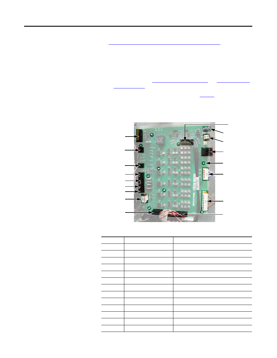
3. Remove remaining wiring harnesses from the power interface board,
including the wiring between the power interface board and the switch
mode power supply board.
Refer to the illustration above for connector locations.
Connector
Wire Color(s)
Connects To:
J1
ribbon
J2 on main control board (ribbon cable)
J2
black
J1 on switch mode power supply board
J6
black
Monitor wire to thermal sensors
J8
red/white/black
J7-U on U phase gate interface board
J9
red/white/black
J1 on 24V power supply board
J10
red/black/white/blue
J3 on precharge board
J12
red/white
J3 on switch mode power supply board
J13
black
J2 on switch mode power supply board
J14
red/white/black
U phase current transducer
J15
red/white/black
V phase current transducer
J16
red/white/black
W phase current transducer
J18
blue/white
U, V, W negative (–) gates (lower phase)
J23
orange/black
U, V, W positive (+) gates (upper phase)
DC input shown
J1
J10
J8
J9
J16
J15
J14
J24
J13
J23
J18
TB2
J6
TB1
J2
Spacers (9)
J12